
24 min read ·
Choose the Right Plug for Your Trailer’s Lights, Brakes, and Power
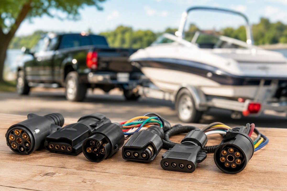
The best way to compare trailer wiring connectors is to ignore the plug name at first and list what the trailer must do. Connector shape and contact count matter only after you know which circuits must pass from the tow vehicle to the trailer.
A seven-position socket is not automatically better than a four-way connector, and a plug that physically fits is not necessarily electrically compatible. The correct choice depends on three facts:
- Which circuits the trailer requires.
- Which circuits the tow vehicle supplies.
- Whether both connectors assign those functions to matching terminals.
Start with the functions your trailer needs
Use this function-first table before shopping for a connector, harness, adapter, converter, tester, or replacement part.
| Trailer requirement | Circuits needed beyond ground | Common starting format | What to verify |
|---|---|---|---|
| Basic lighting only | Running or marker lights, combined left turn/stop, combined right turn/stop | 4-way flat | Vehicle and trailer use compatible combined turn/stop outputs |
| Reverse-triggered surge-brake lockout | Basic lighting plus a reverse-triggered circuit | 5-way flat | Fifth circuit is connected to reverse and reaches the lockout solenoid |
| Conventional electric brakes | Basic lighting plus brake-control output | 6- or 7-way light-vehicle connector | Brake terminal, wiring, and compatible brake controller |
| Reverse lights | Basic lighting plus reverse output | Often 6- or 7-way | Reverse terminal is assigned correctly and active |
| Auxiliary or charge line | Basic lighting plus a 12-volt auxiliary circuit | Often 6- or 7-way | Circuit is installed, active, protected as specified, and suitable for the connected equipment |
| Several added functions | Lighting plus some combination of brakes, reverse, and auxiliary power | Commonly 7-way RV blade | Every required position is correctly wired and active on both sides |
A small trailer that needs only ground, running lights, and combined left and right turn/brake signals commonly uses a 4-way flat. A 5-way flat commonly adds a reverse-triggered line, often used to disable a hydraulic surge-brake actuator while backing. Six- and seven-way light-vehicle connectors can accommodate electric-brake control, reverse, and auxiliary-power circuits, but their exact assignments must be verified. These distinctions are summarized in an overview of North American trailer connectors.
More connector positions do not guarantee more working functions. A seven-way socket may be installed while its brake, reverse, charge, or auxiliary terminals remain unconnected or inactive.
If the trailer has conventional electric brakes, use a connector and tow-vehicle installation that carry a suitable brake-control circuit. The tow vehicle also needs compatible brake-controller equipment and wiring; a basic lighting output and passive adapter cannot substitute for them. An etrailer comparison of 4-way and 7-way functions confirms that electric brakes require an additional circuit and a brake controller.
Do not select wire gauge, circuit protection, or charging arrangements from connector count alone. Those details depend on the vehicle, trailer, controller, connected equipment, routing, and applicable manufacturer instructions. Consult official requirements for the jurisdictions in which the combination will be operated rather than relying on a generic connector guide for legal advice.
Compare 4-way, 5-way, 6-way, and 7-way connector types
The common names describe form and contact count, not guaranteed electrical behavior.
| Connector format | Commonly supported circuits | Common application examples | Main compatibility caution |
|---|---|---|---|
| 4-way flat | Ground, running or marker lights, left turn/stop, right turn/stop | Light trailers needing basic lighting | Does not ordinarily provide conventional electric-brake control, reverse, or auxiliary power |
| 5-way flat | Four basic circuits plus an additional circuit commonly used for reverse | Trailers with reverse-triggered surge-brake lockout | Verify what the fifth terminal actually does |
| 6-pin round | Basic lighting, often with electric-brake and 12-volt auxiliary circuits | Light-vehicle trailers needing added functions | Published arrangements are not universal; terminal use can vary |
| 7-way RV blade | Basic lighting plus positions for brake control, reverse, and 12-volt auxiliary power | Light-vehicle trailers needing several added functions | “7-way” does not prove RV-blade format, pinout, active circuits, or color convention |
| 7-way round-prong | Varies with the particular round-prong arrangement | Installations built around that connector family | Do not assume interchangeability with RV blade |
| 7-way SAE J560 | Heavy-duty truck and trailer signaling and power functions | Heavy-duty trucks and trailers | Distinct from the common light-vehicle RV-blade system |
4-way flat
In common North American light-trailer practice, a 4-way flat carries:
- Ground
- Running, tail, or marker lights
- Combined left turn and stop
- Combined right turn and stop
It is a compact choice when that is the trailer’s complete circuit list. It is not the usual solution for conventional electric brakes, a reverse signal, or auxiliary power.
5-way flat
A 5-way flat commonly retains the four basic lighting functions and adds a circuit associated with reverse. On many boat-trailer installations, that reverse signal operates a surge-brake lockout so the trailer can be backed without the actuator applying the brakes.
Do not infer the fifth function from shape alone. Trace it or consult the equipment documentation. Some five-way vehicle sockets can physically accept a four-way trailer plug, but only the four shared circuits are then available, as the North American connector overview cited above explains.
6-pin round
A 6-pin round connector may add brake control and 12-volt auxiliary power to the basic lighting functions. Because published arrangements vary, copying a generic diagram can cross brake, power, reverse, or lighting functions.
Before replacing or rewiring one, identify:
- The precise six-pin connector family
- Vehicle side or trailer side
- Mating-face or wire-entry view
- Function assigned to every terminal
- Vehicle outputs that are actually active
7-way RV blade
The common light-vehicle 7-way RV blade can carry the four basic lighting functions plus electric-brake control, reverse, and a 12-volt auxiliary circuit. A manufacturer’s trailer wiring guide distinguishes RV-blade, round-prong, and differing RV color arrangements, showing why “seven wires” is not a complete wiring instruction.
Seven positions provide capacity for seven circuits. They do not prove that the vehicle has a brake controller, that an auxiliary line is energized, or that the reverse circuit has been connected.
7-way round-prong and SAE J560
A seven-way round-prong connector is a separate family from the common RV blade. SAE J560 is another seven-contact system associated with heavy-duty trucks and trailers, not another name for the light-vehicle RV-blade connector.
Some heavy-duty connector systems may look similar or even appear to mate. Do not treat physical similarity as proof of electrical compatibility. The available secondary overview distinguishes SAE J560 from ISO 1185 and reports differences in their electrical arrangements; verify the current applicable standard and authoritative equipment drawings before attempting any conversion.
Shopping terminology translated
- Pin, pole, or way: Terms commonly used for the number of electrical positions. Retail wording is not always consistent.
- Flat: Contacts arranged in a flat molded body, as with common 4- and 5-way connectors.
- Blade: Flat contact elements, especially in the common 7-way RV-blade family.
- Round: May describe a round housing, round contacts, or both. It does not identify one universal arrangement.
- Plug: Usually the movable connector attached to the trailer cable.
- Socket or receptacle: Usually the fixed vehicle-side connector.
- Vehicle end: Hardware or wiring intended for the tow vehicle.
- Trailer end: Hardware or wiring intended for the trailer.
- Mating face: The side that connects to the opposite connector.
- Wire-entry side: The rear where conductors attach. A diagram from this side is mirrored relative to a mating-face view.
Retail catalogs list connectors from two through seven ways, along with plugs, sockets, adapters, kits, harnesses, wire, and testers. That breadth shows what product categories exist, not which product fits a specific installation. One specialty trailer-products catalog, for example, separates products by way count and includes vehicle-end, trailer-end, flat, round, RV-blade, adapter, kit, and tester categories.
Why two connectors that fit may still be incompatible
Compatibility has four layers, and all four must pass:
- Connector family and physical fit: Do the plug and socket belong to the same system?
- Terminal functions: Does each position carry the same function at both ends?
- Active source circuits: Does the tow vehicle energize the required terminal under the appropriate condition?
- Equipment requirements: Is the circuit suitable for the controller, actuator, lighting, or auxiliary equipment connected to it?
A physical connection answers only the first question.
“7-way” is not one connector specification
The label can refer to RV blade, round-prong, or heavy-duty systems. Even within light-vehicle RV wiring, published SAE and traditional color assignments differ, particularly for tail, turn/stop, reverse, and auxiliary-power conductors.
Wire colors are therefore clues, not proof. They become especially unreliable on homemade trailers, imported equipment, previous-owner modifications, or repairs made with whatever wire was available.
Any connector diagram used for repair should explicitly identify:
- Connector family
- Vehicle or trailer side
- Mating-face or wire-entry view
- Function assigned to each terminal
Without those labels, a correctly drawn diagram can still be applied backward or to the wrong connector. For that reason, there is no unlabeled “universal 7-way pinout” in this guide.
Before moving a conductor, compare the applicable connector drawing with the tow-vehicle and trailer documentation, then verify actual terminal behavior. If the records disagree with the installation, stop and trace the circuit. A previous repair may have changed the original arrangement.
Adapter, converter, harness, or replacement connector?
These products solve different problems. Selecting the right category is as important as selecting the connector family.
Passive adapter
A passive adapter joins two physical formats and passes through circuits shared by both ends. It can route an existing signal to a corresponding terminal, but it cannot generate brake-control output, reverse, charging, or auxiliary power that the vehicle does not supply.
Use one when:
- Both connector families are known.
- Required source functions are present and active.
- The adapter maps those functions correctly.
- Losing any unshared circuits is acceptable.
Electrical converter
A converter changes signal architecture. A common example is adapting separate vehicle brake and turn signals to the combined turn/stop arrangement used by many light trailers.
That is different from changing plug shape. Select the converter for the specific vehicle architecture and install it according to the vehicle and product instructions rather than assuming every connector kit performs the same conversion.
Vehicle-specific custom harness or T-connector
A custom harness is designed for a particular vehicle application and connects to existing wiring without cutting or splicing. It generally provides a standard trailer output. Some vehicles instead have a manufacturer-provided socket for a custom connector or standardized harness interface.
Fitment remains essential. A retailer prompt can narrow a catalog, but it does not replace checking:
- Exact vehicle configuration
- Factory tow package or prewiring
- Connector location
- Product instructions
- Supported output functions
Splice-in harness or taillight converter
When no suitable plug-in interface exists, a splice-in harness or taillight converter may connect to the vehicle’s lighting circuits. Correct signal identification is essential, and installation should follow vehicle-specific instructions. Visual wire matching alone is insufficient.
The CURT guide cited earlier treats custom plug-in harnesses, splice-in converters, and replacement wiring as separate installation approaches.
Replacement plug or socket
A damaged trailer-side plug or vehicle-side socket can often be replaced without rewiring the entire trailer. Match the replacement to:
- Connector family
- Vehicle or trailer end
- Terminal arrangement and orientation
- Cable and conductor requirements
- Mounting method
- Environmental exposure
- Applicable installation instructions
Replacement is appropriate when the housing, terminals, contacts, cable clamp, or cover can no longer provide a secure connection.
Complete wiring kit
A kit may contain a connector, cable, terminals, splices, converter, mounting hardware, tester, or instructions. Contents vary. The word kit does not prove that the package provides brake-control wiring, battery charging, or everything required for a particular vehicle.
Dual-output socket
Vehicle sockets offering both 7-way RV-blade and 4-way-flat outputs are sold for installations that tow different trailers. They may reduce adapter use, but each output still needs to be tested. A dual housing cannot activate circuits that were never installed.
Five-step product selection flow
- Identify the vehicle output. Record connector family, end, viewing orientation, and every active function.
- Identify the trailer input. Record the same details and trace uncertain conductors.
- List every required function. Include basic lighting, brake control, reverse, lockout, and auxiliary or charging needs.
- Test the vehicle circuits. Confirm which outputs operate under the relevant conditions.
- Choose the least complex product that preserves every requirement. Use a passive adapter only for a physical mismatch between compatible shared functions; use a converter or additional wiring when electrical behavior must change.
What adapters preserve—and what they cannot add
Describe an adapter by direction: tow-vehicle output first, trailer input second. “4-to-7” should mean a four-way vehicle output feeding a seven-way trailer input, not merely a product with those two connectors.
| Adapter direction | Functions it can commonly preserve | Functions it cannot create | Required verification |
|---|---|---|---|
| 7-way vehicle to 4-way trailer | Ground and the trailer’s four basic lighting circuits | Functions the 4-way trailer does not accept | Source family, active outputs, ground, and adapter mapping |
| 4-way vehicle to 7-way trailer | Ground and basic lighting when correctly mapped | Brake control, charging, reverse, or auxiliary functions | Whether separate wiring and equipment are required |
| 6-way vehicle to 7-way trailer | Functions correctly mapped and active at the six-way source | Any absent source circuit | Both terminal arrangements and adapter mapping |
| 7-way vehicle to 6-way trailer | Shared functions that are active and correctly mapped | Any function omitted by the six-way input | Both terminal arrangements and post-connection operation |
7-way vehicle to 4-way trailer
A suitable adapter can pass the four shared basic-lighting circuits from an active, correctly wired seven-way vehicle socket to a four-way trailer. Brake, reverse, and auxiliary positions have nowhere to go at the four-way trailer connection.
This is often a straightforward format conversion, but the trailer lights still need to be checked before towing.
4-way vehicle to 7-way trailer
A passive adapter can make the connectors mate and route basic lighting signals to the corresponding seven-way positions. It cannot independently create electric-brake output, a charge line, reverse, or auxiliary power.
Conventional electric brakes still require the additional brake circuit, suitable installation wiring, and a compatible controller. A seven-way receptacle may therefore be physically installed while functioning electrically as little more than a four-way.
6-way to 7-way and 7-way to 6-way
These conversions require tracing. Different installations may assign brake control, auxiliary power, or other functions to different positions. An adapter advertised only by contact count does not prove that it maps the source and destination conventions correctly.
Before use:
- Identify both connector families.
- Obtain correctly oriented terminal drawings.
- Test each source function.
- Confirm the adapter’s internal mapping.
- Connect the trailer.
- Test every required function again.
A successful physical connection is not the final verification step.
A practical connector buying checklist
Use this checklist before ordering or opening a wiring package.
Identity and orientation
- [ ] Exact connector family is identified.
- [ ] Position count is correct.
- [ ] Vehicle-side or trailer-side part is specified.
- [ ] Plug or socket/receptacle is correct.
- [ ] Product diagram states mating-face or wire-entry view.
- [ ] Seller terminology agrees with the actual housing and contacts.
- [ ] Existing connector has been inspected rather than identified from a generic photo alone.
Required functions
- [ ] Ground
- [ ] Running, tail, and marker lights
- [ ] Left turn/stop
- [ ] Right turn/stop
- [ ] Reverse-triggered lockout, if fitted
- [ ] Reverse lights, if fitted
- [ ] Electric-brake control, if fitted
- [ ] Auxiliary or charge line, if required
- [ ] Any equipment-specific circuit documented by the trailer manufacturer
Select by circuits, not merely trailer size or contact count. Similar-looking trailers may need different connectors because their brake, reverse, and auxiliary systems differ.
Vehicle fitment
- [ ] Confirm whether a factory or standardized socket is already present.
- [ ] Check for a factory tow package or prewiring.
- [ ] Match a custom harness to the exact vehicle configuration.
- [ ] Read the manufacturer’s installation instructions before purchase.
- [ ] Verify whether a signal converter is required.
- [ ] Do not treat a product title or retailer fitment prompt as final proof.
Mounting and routing
- [ ] Socket mounting style fits the vehicle.
- [ ] Bracket hole pattern and clearance are suitable.
- [ ] Cover can open fully with hitch equipment installed.
- [ ] Cable is long enough without being pulled tight.
- [ ] Routing avoids exhaust, sharp edges, pinch points, and moving parts.
- [ ] Strain relief or a cable clamp protects conductors near the connector.
- [ ] Harness support prevents dragging and keeps cable weight off the terminals.
Retail categories list brackets, clips, connectors, adapters, harnesses, kits, and testers separately, so confirm what the package includes rather than assuming mounting hardware is supplied. AutoZone’s trailer-wiring category page illustrates these categories but does not establish fitment for a particular vehicle.
Electrical specifications
- [ ] Conductor gauge is verified against vehicle, trailer, controller, and equipment documentation.
- [ ] Connector and terminal ratings suit the intended circuits.
- [ ] Cable construction suits the routing and exposure.
- [ ] Circuit protection follows the applicable instructions.
- [ ] Brake-controller and auxiliary-power requirements are documented.
- [ ] Any charging arrangement is suitable for the connected battery or equipment.
There is no responsible universal gauge, fuse, or charging specification based solely on “4-way,” “6-way,” or “7-way.”
Environment and construction
- [ ] Housing is intact and suitable for its mounting location.
- [ ] Vehicle socket has a usable cover where needed.
- [ ] Cable entry and strain relief fit the cable diameter.
- [ ] Terminal materials and corrosion-resistance descriptions are documented.
- [ ] Any sealing or moisture-resistance claim applies to the completely assembled connector.
- [ ] Replacement seals, covers, or terminals are available where the design is serviceable.
Treat terms such as weatherproof, heavy duty, and corrosion resistant as manufacturer or retailer claims unless tied to a relevant specification and correct installation conditions. No connector design eliminates the need for clean contacts, secure terminals, cable support, and sound grounds.
Serviceability
- [ ] Replacement contacts or terminal screws are available.
- [ ] Conductors can be secured with the specified method and tools.
- [ ] A cracked housing can be replaced.
- [ ] Individual terminals can be serviced where the design permits.
- [ ] Instructions state the termination and assembly method.
- [ ] The connector can be inspected after assembly.
Price, stock, discounts, review counts, and broad marketing claims are not substitutes for specifications or confirmed fitment.
Keep a purchase record
Write down:
- Connector family
- Vehicle or trailer end
- Plug or socket
- Diagram viewing orientation
- Terminal-to-function map
- Active tow-vehicle functions
- Source of product ratings
- Applicable vehicle, trailer, and component instructions
That record will make later testing or repair substantially easier.
Verify the connector before relying on it
Useful diagnostic tools include:
- A connector-specific tester
- A 12-volt test light
- A DC multimeter
Start at the disconnected tow-vehicle socket. That separates a vehicle-output problem from a fault downstream on the trailer.
Safety before energized testing
Follow the tow-vehicle and brake-controller manufacturer’s prescribed test method. Keep the vehicle parked and immobilized, and do not place it in gear merely to obtain a reverse-terminal reading. If the required output cannot be activated safely while stationary, use the applicable service procedure or seek qualified assistance.
Keep meter probes from bridging adjacent contacts. Stop if the connector drawing, terminal identity, or safe activation method is uncertain.
Energized voltage tests
- Identify the connector family and orientation. Use the correct vehicle-side drawing.
- Identify ground. Confirm it through documentation or tracing; do not guess from position or color.
- Set the multimeter to DC voltage.
- Connect the reference lead to the verified ground.
- Activate one safe, applicable function at a time.
- Measure the associated terminal without contacting neighboring terminals.
- Record the result before moving to the next function.
This method—verifying ground, selecting DC voltage, activating one function at a time, and probing the corresponding vehicle terminal—is described in a multimeter trailer-light testing guide.
A connector-specific tester can indicate several common vehicle-side functions without connecting the trailer, but it must match the actual connector family. An RV-blade tester does not validate a round-prong or heavy-duty arrangement.
A test light can show whether a lighting output is present, while a multimeter provides a numerical reading. Use either tool according to its instructions.
Power-off continuity and resistance tests
Keep continuity testing separate from energized voltage testing:
- Disconnect power and isolate the relevant circuit.
- Set the meter to continuity or resistance as appropriate.
- For a trailer-ground check, measure between the trailer ground conductor and a clean frame-ground point where that grounding method applies.
- For an individual conductor, isolate both ends before checking continuity.
- Interpret the reading using the equipment documentation and known test-lead resistance.
Power-off ground and wire-continuity testing are also described in the multimeter guide cited above. Do not measure resistance or continuity on an energized circuit.
Use the result to locate the fault
- No correct output at the vehicle socket: Diagnose the vehicle wiring, controller, converter, protective device, configuration, or harness according to vehicle-specific instructions.
- Correct output at the socket but not beyond the trailer plug: Inspect mating contacts, terminal security, corrosion, moisture, and wiring near the plug.
- Voltage reaches a nonworking light: Inspect the bulb, LED assembly, socket, connector, and local ground.
- No voltage reaches the light: Trace the circuit upstream through the harness and junctions.
- Reading changes when the cable moves: Inspect for loose terminals, failed strain relief, or a conductor broken inside the insulation.
External-battery testing is not covered here. A safe procedure requires verified polarity, circuit identification, suitable fused protection, and short-circuit precautions. Use an applicable service manual or qualified technician if vehicle-independent power testing is necessary.
Pre-tow functional check
After any installation, repair, or adapter change, verify the following from a safely parked vehicle:
- Running and marker lights
- Left turn signal
- Right turn signal
- Brake lights
- Electric-brake output and controller operation, where fitted, using the controller maker’s procedure
- Reverse lights or surge-brake lockout, where fitted, using a safe prescribed method
- Auxiliary or charge-line operation, where required
A trailer-dealer testing guide likewise recommends checking lighting and signaling functions before towing. Test functions individually and in relevant combinations; the job is not complete merely because the plug latches.
Troubleshoot and maintain the connection from front to back
Use a fixed diagnostic order:
- Tow-vehicle socket
- Trailer plug
- Ground
- Main cable or harness
- Junctions and branches
- Individual light or electrical load
This sequence helps locate the first point where a known-good signal disappears.
| Symptom | First test | Likely inspection points | Next step |
|---|---|---|---|
| All lights dead | Test vehicle lighting outputs and verify ground | Vehicle socket, adapter, trailer plug, main ground | Repair the first point where the signal disappears |
| One side dead | Test that side’s turn/stop output at the vehicle socket | Matching terminal, branch wire, junction, lamp, local ground | Compare working and failed sides |
| Flickering or dim lights | Check ground and observe readings while connections are gently moved | Corrosion, loose terminals, damaged conductors, frame grounds | Repair insecure connections and retest under load |
| Left and right reversed | Identify live terminals electrically | Prior repairs, adapter mapping, crossed conductors | Move wires only after confirming both functions |
| Intermittent when cable moves | Inspect near the plug and strain relief | Broken strands, loose clamp, pulled terminal, cracked housing | Replace the damaged cable section or connector |
| Electric brakes fail | Verify controller status and brake output using prescribed procedures | Brake terminal, adapter limitations, wiring, junctions, brake system | Follow controller and brake-system diagnostics |
| Auxiliary power absent | Test the designated terminal under the required conditions | Inactive source circuit, protection device, terminal, wiring | Consult vehicle and auxiliary-equipment instructions |
All lights are dead
Do not begin by replacing every lamp. First confirm that the vehicle socket supplies the basic outputs and that the ground path is intact. Then inspect the adapter, trailer plug, and main trailer ground.
If the vehicle socket fails, keep the trailer disconnected while diagnosing the vehicle side. If the socket passes, work downstream until the signal disappears.
One side is dead
A failed left or right circuit can originate at the vehicle output, connector terminal, branch splice, cable run, lamp assembly, or local ground. Compare the failed side with the working side, but do not assume their wire colors are correct.
Lights are dim or flicker
Inspect grounds, loose terminals, corrosion, damaged wire, and insecure junctions. A working lamp assembly can still be dim when poor connections prevent useful voltage from reaching it under load.
Check for ground lugs installed over paint, rust, or contamination; loose fasteners; damaged ground wire; and connector contacts that no longer remain secure. Repair according to the applicable component instructions and retest.
Left and right signals are reversed
Activate one side at a time and identify which terminal becomes live. Trace the function through the adapter, plug, junctions, and branch wires. Move conductors only after locating where the crossing occurred.
Conventional colors may suggest the likely mistake, but color alone is not proof. Published seven-way color schemes differ, and previous repairs may follow no recognized convention.
Operation changes when the cable moves
Concentrate on:
- Conductors broken near the plug
- Terminals pulling out of the housing
- Loose terminal screws
- Failed cable clamps or strain relief
- Cracked housings
- Adapter contacts with poor retention
- Harness chafing near supports or frame openings
Electric brakes fail
First confirm that the trailer uses conventional electric brakes and that the tow vehicle has the intended controller and wiring. Verify brake output only under the controller manufacturer’s test conditions.
If a passive 4-way-to-7-way adapter was recently installed, its seven-way receptacle should not be assumed to provide brake output. Trace the circuit from the controller to the vehicle socket, through the plug and cable, and onward to the trailer junction and brake wiring.
Auxiliary power is absent
Confirm that the terminal is assigned to auxiliary or charging use in this particular connector arrangement. Then determine when the vehicle is intended to energize it. The output may depend on the vehicle’s configuration or control strategy.
A visible seven-way socket does not establish that this circuit is active.
Voltage is present at a nonworking light
Inspect the bulb, LED assembly, socket, local connector, and local ground. Voltage measured relative to one reference point can coexist with a failed return path at the lamp. If no voltage is present, trace upstream toward the last known-good junction.
Inspect the hardware, not just the readings
At the plug and socket, check for:
- Corrosion or surface contamination
- Moisture and dirt
- Bent, recessed, or loose terminals
- Cracked or distorted housings
- Damaged covers or latches
- Failed cable clamps and strain relief
- Broken conductors immediately behind the connector
Along the harness, inspect for:
- Cuts and kinks
- Fraying or chafing
- Exposed insulation
- Unsupported routing
- Pinch points
- Loose junctions
- Repairs under tension
- Contact with sharp, hot, or moving parts
Peterson’s harness inspection guide recommends checking connectors, junctions, grounds, chafing, cuts, and loose connections. Treat any stated inspection interval as that manufacturer’s recommendation, not a universal rule; use the schedule specified for your equipment and service conditions.
Light surface contamination may be cleanable when contacts remain intact and secure. Repair or replace a connector when:
- A terminal cannot be secured correctly.
- Corrosion has materially damaged the contact.
- A contact is bent, recessed, loose, or badly eroded.
- The housing is cracked or distorted.
- The latch or cover no longer functions.
- Strain relief no longer protects the conductors.
- Wiring is broken too close to the connector for a sound termination.
Grease, coatings, covered sockets, sealed lights, and corrosion-resistant materials may be useful when applied as their manufacturers direct. None can compensate for contaminated mating surfaces, loose terminals, damaged seals, failed grounds, or poor cable support.
Frequently Asked Questions
Are all 7-way trailer wiring connectors wired the same?
No. “7-way” can describe RV-blade, round-prong, and heavy-duty connector families. Their terminal arrangements are not interchangeable by assumption, and published RV-blade wire-color conventions also differ.
Identify the connector family, side, and diagram orientation, then verify each function before moving wires.
Can I use a 4-way-to-7-way adapter to operate electric trailer brakes?
Not by itself. A passive adapter can route basic lighting circuits into a seven-way receptacle, but it cannot generate brake-control output.
Conventional electric trailer brakes require an additional brake circuit, suitable wiring, and a compatible tow-vehicle brake controller. Adapter products with extra leads provide those functions only after the larger installation is completed correctly.
Can I identify trailer connector functions by wire color alone?
No. Color is a clue, not proof. Seven-way conventions differ, and modified, imported, homemade, or repaired trailers may use other colors.
Confirm functions with a correctly labeled connector drawing, equipment documentation, terminal tracing, or electrical testing.
How do I determine whether a trailer wiring fault is on the vehicle or trailer?
Begin at the disconnected tow-vehicle socket. Identify ground, activate one safe function at a time, and test the corresponding output.
If the correct signal is absent there, diagnose the vehicle side. If the socket tests correctly, work downstream through the trailer plug, ground, harness, junctions, and individual loads.
When should a corroded trailer plug or socket be replaced?
Cleaning may be reasonable for light surface contamination when the contacts remain structurally sound and secure. Replace or rebuild the connector when corrosion has compromised a contact, a terminal is loose or badly deformed, the housing is cracked, or the cable clamp and strain relief no longer protect the wiring.
After cleaning or replacement, verify terminal retention, ground integrity, and every required function under normal operating conditions.
The final rule is simple: list every circuit the trailer requires, identify the exact connector family and orientation on both sides, verify which tow-vehicle circuits are active, and choose hardware that preserves those functions. Adapters solve physical mismatches only within the limits of the wiring already present. Test every repaired or adapted setup function by function before towing.