
20 min read ·
How to Identify and Wire the Right Seven-Circuit Trailer Connection
Before moving a wire, match the connector family, vehicle socket or trailer plug, and contact-face or rear wire-entry view to the diagram in front of you.
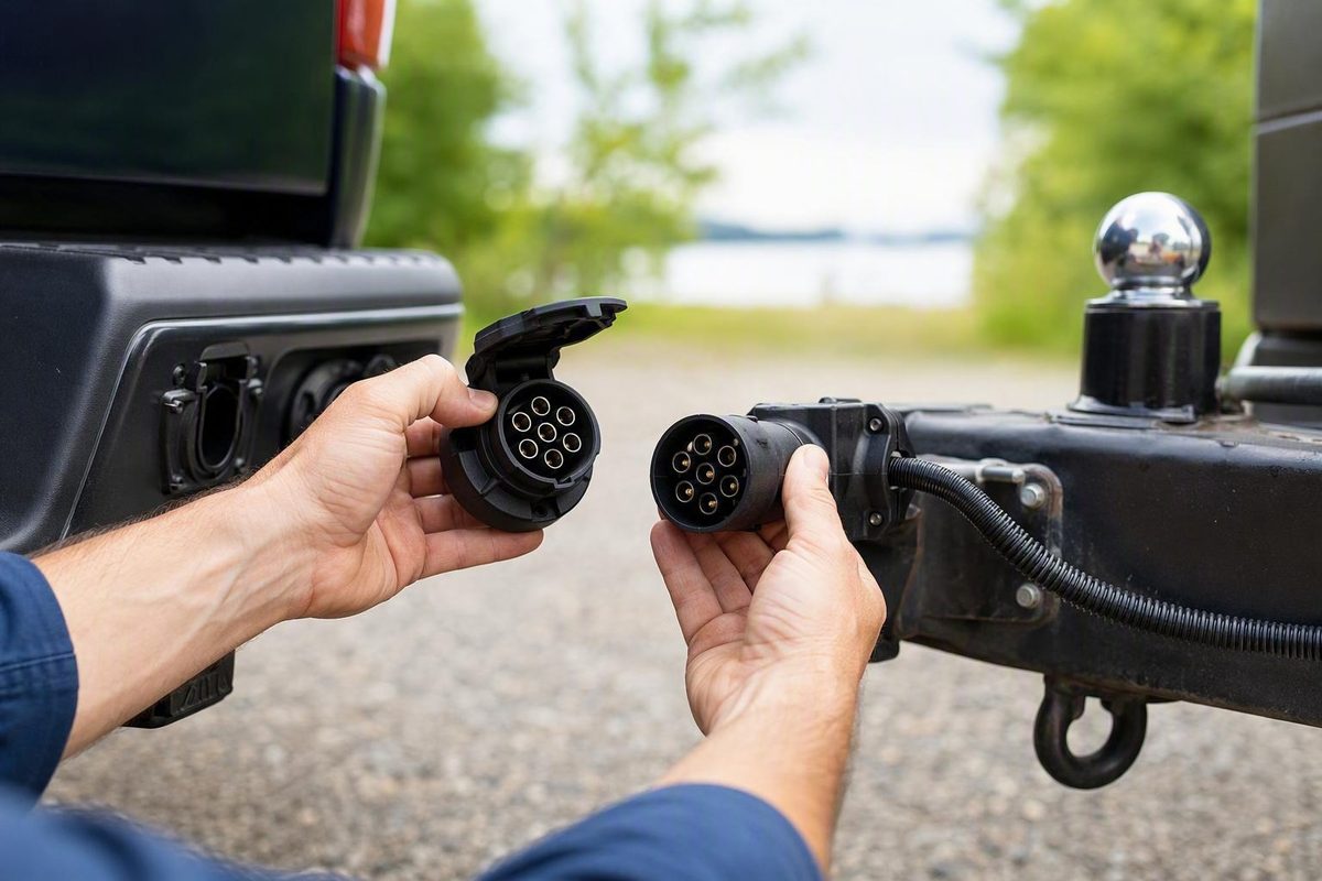
A useful 7 way trailer connector wiring diagram begins with circuit functions—not insulation colors or an assumed physical pin arrangement. Before moving a wire, identify the connector family, determine whether you are working on the vehicle socket or trailer plug, and confirm whether the applicable diagram shows the contact face or the rear wire-entry side.
This guide covers circuit identification, testing, replacement, and troubleshooting for the common North American RV-style seven-way blade connection. It does not claim that one physical terminal-position drawing applies to every seven-contact connector. Exact terminal locations must come from the molded labels and documentation for the connector in your hands.
Master warning: Improper connections can damage electrical components. Confirm every terminal from the connector markings, its installation sheet, and the applicable tow-vehicle and trailer documentation before applying power. Wire color alone is not proof of function. etrailer’s wiring guide likewise recommends identifying circuits with a tester because colors vary by manufacturer.
Start Here: What a North American 7-Way Connection Usually Carries
A typical North American RV-style seven-way connection provides seven separate electrical paths:
TOW VEHICLE                                      TRAILER
───────────                                      ───────

Verified ground  ──────────────────────────────  Trailer ground

Tail/running     ──────────────────────────────  Tail, marker,
lights                                           clearance and
                                                 license lights

Left stop/turn   ──────────────────────────────  Left brake/turn lamps

Right stop/turn  ──────────────────────────────  Right brake/turn lamps

Brake-controller
output           ──────────────────────────────  Electric brake circuit

Protected 12 V
auxiliary feed   ──────────────────────────────  Supported charging
                                                 or accessory circuit

Reverse signal   ──────────────────────────────  Reverse lamps or
                                                 surge-brake lockout
Diagram scope: Functional circuit diagram only. Connector family: typical North American RV-style seven-way blade. Side: vehicle and trailer. View: no physical terminals shown. This diagram does not establish terminal positions.
The expected functions are:
- Ground
- Tail and running lights
- Left stop and turn
- Right stop and turn
- Electric-brake controller output
- 12-volt auxiliary power
- Reverse lights or surge-brake lockout, where applicable
North American light-vehicle trailer wiring commonly combines the brake-light and turn-signal functions. Instead of carrying one brake circuit plus two independent turn circuits, the connector normally provides a combined left stop/turn circuit and a combined right stop/turn circuit. The additional contacts can then carry electric-brake output, auxiliary power, reverse-related operation, and ground. These seven general functions are described in CURT’s configuration-specific trailer wiring guide.
Two circuits must remain distinct:
- Electric-brake output is the controlled output sent from the tow vehicle’s brake controller to the trailer brake circuit.
- 12-volt auxiliary power is a separate supply for supported trailer equipment or charging arrangements.
Neither is a substitute for the other. Do not connect either circuit until its identity and intended use have been confirmed.
The functional schematic above can help you test and label wires, but it cannot tell you where a function sits on an unidentified connector. A physical pinout is usable only when it states all of the following:
- Connector family and configuration
- Tow-vehicle socket or trailer plug
- Front contact face or rear wire-entry side
- Direction from which the connector is being viewed
Identify the Connector Before Choosing a Diagram
“Seven-pin” and “seven-way” describe the number of contacts. They do not establish that two connectors share the same shape, terminal layout, or circuit assignments.
North American RV-style blade
The common North American RV-style connector uses flat blade contacts. It may be described as a:
- Seven-way RV blade
- Seven-pole RV connector
- Seven-way blade connector
- RV-style seven-pin connector
This flat-blade style is common on newer North American trucks and SUVs equipped with factory towing systems. It commonly supports trailer lighting, electric brakes, auxiliary power, reverse-related functions, and ground.
Even within the RV-blade category, however, published “traditional” and SAE-oriented configurations can use different color conventions. Identify the exact connector and follow its own labels rather than selecting a diagram solely because the housing looks familiar.
Seven-way round-prong connector
A seven-way round-prong connector uses round contacts instead of the flat blades found in the common RV-style connection. It requires a diagram specifically identified for that connector.
Do not treat it as an RV-blade connector with different-shaped contacts. Published round-prong and RV-blade examples assign some colors differently, and their physical terminal placement is not interchangeable.
Light-vehicle blade versus heavy-truck round-pin systems
The RV-style blade connection used on North American light vehicles is also distinct from the SAE J560-style round-pin connection associated with heavy-truck applications. The systems serve different applications and do not share a pinout merely because both have seven contacts.
The supplied evidence identifies SAE J2863 with a light-vehicle blade application and discusses SAE J560 separately for heavy trucks. Because that distinction is based here on a tertiary North American connector overview, use the applicable connector or vehicle manufacturer’s documentation—not the overview itself—to make physical terminal assignments.
European seven-pin lighting connector
A European seven-pin lighting connector is a separate system. One common European arrangement carries:
- Left turn signal
- Right turn signal
- A separate brake-light circuit
- Divided tail-light circuits
- Rear fog light
- Ground
That differs fundamentally from the typical North American RV-style arrangement, which uses combined left and right stop/turn circuits and commonly includes electric-brake output and auxiliary power.
A standard European seven-pin lighting setup generally lacks dedicated reverse and additional-power circuits. European 13-pin systems are commonly used when reverse lights or extra power functions are required, according to TrailerPlus’s comparison of seven-pin and 13-pin systems.
Diagram-selection checklist
Before using a physical terminal drawing, answer all four questions:
| Check | What to identify | Why it matters |
|---|---|---|
| Region and application | North American light vehicle, heavy truck, or European system | Seven-contact systems can carry different functions |
| Contact type | Flat blade or round prong | Equal contact counts do not establish a shared layout |
| Connector side | Tow-vehicle socket or trailer plug | Mating contact faces can appear mirrored |
| Viewing side | Front contact face or rear wire-entry side | Opposite sides of one connector appear reversed |
If any answer is unknown, stop before assigning conductors. Look for a part number, molded function labels, installation sheet, or manufacturer diagram.
The Seven Circuits, Explained One by One
Understanding each circuit makes it easier to identify an unknown harness and distinguish a wiring fault from an incorrect terminal assignment.
1. Ground
Ground is the return path for the connected trailer loads. Lighting, brake, auxiliary, and reverse circuits depend on a reliable return path to operate correctly.
Use a dedicated ground conductor between the vehicle and trailer connector. Do not rely on incidental contact through the hitch ball as the primary electrical return. Movement, coatings, corrosion, and contamination can make that contact inconsistent. AJ’s Truck and Trailer Center also recommends a dedicated ground sized for the connected load in its RV-style seven-way guidance.
On the trailer, check both the main ground connection and the local grounds used by individual lamps or equipment. A sound connector ground cannot correct a poor connection at a particular device.
2. Tail and running lights
Depending on the trailer, it may serve:
- Tail lamps
- Side-marker lamps
- Clearance lamps
- Identification lamps
- License-plate illumination
Because several lamps can share this circuit, the fault pattern matters.
3. Left stop and turn
This circuit carries the trailer’s left turn indication and, in a typical North American combined-light system, the left brake-light command.
With the left turn signal active, the circuit should pulse. With the service brakes applied and no turn signal selected, it should carry the left brake-light command.
4. Right stop and turn
The corresponding right-side circuit carries the right turn indication and right brake-light command.
Test the left and right circuits independently. If both sides flash together, one lamp glows dimly, or one function changes when another is switched on, inspect the ground path and crossed or damaged wiring before assuming that both vehicle outputs have failed.
5. Electric-brake output
The electric-brake terminal carries controlled output from the tow vehicle’s brake controller to the trailer brake circuit. It is not simply a steady battery supply.
It is also different from the brake-pedal or brake-light-switch input used by some aftermarket controller harnesses. A controller can receive power, ground, and a brake-pedal signal through separate wires while sending a distinct controlled output toward the trailer.
6. 12-volt auxiliary power
The auxiliary terminal is a separately supplied power feed. Depending on the vehicle and trailer design, it may support:
- A compatible trailer-battery charging arrangement
- Interior lighting
- Cameras or monitoring equipment
- Relays
- A supported tongue jack or other accessory
These are possible uses, not evidence that every auxiliary circuit can operate every device.
The feed may be continuously energized, ignition-controlled, relay-controlled, or enabled only under specified vehicle conditions. Verify the actual design before modifying it.
7. Reverse lights or surge-brake lockout
The remaining circuit commonly serves trailer reverse lamps or a reverse-triggered surge-brake lockout. Not every trailer uses either feature, and an unused conductor may have been repurposed during a previous repair.
Treat the circuit as unconfirmed until tested. Do not assume that a center contact, seventh terminal, yellow wire, or purple wire always means reverse.
Let the specifications govern circuit capacity
There is no responsible universal wire-size, fuse, or breaker recommendation for every seven-way installation. The correct selection depends on:
- Actual current
- Circuit length
- Acceptable voltage drop
- Duty cycle
- Environmental conditions
- Terminal and connector ratings
- Vehicle integration
- Brake-controller requirements
- Accessory manufacturer instructions
Follow the specifications for the vehicle, connector, controller, protective device, and connected equipment. Do not increase a fuse or breaker rating merely because an existing protective device opens under load.
Typical Wire Colors—and Why They Are Not a Pinout
Wire colors are conventions, not conclusive identifiers. Manufacturers can use different schemes, replacement cords may not match original harnesses, and previous owners may have used whichever conductor color was available.
The following comparison comes from separately labeled CURT configurations. It compares conductor colors by function; it does not show physical terminal locations.
| Circuit function | RV blade: SAE example | RV blade: traditional example | Round-prong example |
|---|---|---|---|
| Ground | White | White | White |
| Tail/running lights | Brown | Green | Brown |
| Left stop/turn | Yellow | Red | Yellow |
| Right stop/turn | Green | Brown | Green |
| Electric brakes | Blue | Blue | Blue |
| 12-volt auxiliary power | Orange | Black | Red |
| Reverse lights | Grey | Yellow | Black |
Table scope: Configuration-specific color comparison only. No plug, socket, contact-face, or wire-entry positions are represented.
The differences are significant:
- Green can mean right stop/turn or tail lights.
- Brown can mean tail lights or right stop/turn.
- Yellow can mean left stop/turn or reverse.
- Auxiliary power can be orange, black, or red in the listed examples.
Another SAE J2863-oriented summary lists this typical practice:
| Typical color | Listed function |
|---|---|
| White | Ground |
| Yellow | Left stop/turn |
| Brown | Tail, marker, clearance, and license lamps |
| Black | Switched 12-volt power |
| Green | Right stop/turn |
| Blue | Electric-brake control |
| Purple | Reverse lamps or surge-brake lockout |
Table scope: Typical light-vehicle blade color practice, not a universal color code or physical pinout.
Use this identification priority:
- Measured or traced electrical function
- Molded terminal marking
- Connector manufacturer’s diagram
- Vehicle and trailer documentation
- Wire color as a supporting clue only
If a black conductor tests as reverse and a yellow conductor traces to auxiliary equipment, connect them according to the verified functions—not a generic chart.
Vehicle Socket vs. Trailer Plug: Avoid the Mirrored-View Error
The vehicle socket and trailer plug mate face to face. When viewed directly into their contact faces, one can appear mirrored relative to the other. Looking at the rear wire-entry side creates another reversal.
Four views are possible:
- Vehicle socket viewed into its mating contacts
- Vehicle socket viewed from the rear wire-entry side
- Trailer plug viewed into its mating contacts
- Trailer plug viewed from the rear wire-entry side
A physical diagram can therefore be accurate but unsuitable for the view in front of you. Do not “fix” an unlabeled online diagram by mentally flipping it. Without its connector family, side, and viewing direction, you cannot know whether it should be reversed.
Orientation caption template
Every physical terminal illustration should include:
Connector family: [RV blade / round-prong / SAE J560 / European seven-pin] Connector side: [tow-vehicle socket / trailer plug] View: [front contact face / rear wire-entry side] Viewing direction: [looking into mating contacts / looking forward from cable entry]
If an illustration omits any of those details, do not use it to place conductors.
Before removing old wires
Inspect the connector for molded words, symbols, or abbreviations identifying ground, lighting, brakes, auxiliary power, left, right, or reverse. Compare those markings with the installation sheet for the exact part.
For replacement work:
- Photograph the connector and existing wire arrangement.
- Mark each conductor before loosening it.
- Record its actual insulation color.
- Verify its electrical function.
- Record the terminal marking.
- Transfer one confirmed function at a time.
This preserves useful evidence from the old installation without treating its color choices as a standard.
How to Verify Every Circuit With a Tester
Use a circuit tester, 12-volt test light, or multimeter to identify functions rather than relying on color. Use voltage testing for an energized vehicle socket. Reserve continuity or resistance testing for a trailer harness that has been disconnected from all applicable power sources.
Testing the vehicle socket
Secure the vehicle and follow its operating instructions whenever a test requires the ignition, service brakes, reverse selection, or brake controller. Keep the connector disconnected from the trailer while identifying vehicle-side outputs unless the vehicle documentation requires trailer detection.
Identify one function at a time:
-
Establish a ground reference. Use a known vehicle chassis ground for the tester’s reference.
-
Activate the running lights. Find the contact that becomes steadily energized with the parking or headlamps.
-
Activate the left turn signal. Identify the contact with the matching left-turn pulse.
-
Activate the right turn signal. Find the separate contact with the right-turn pulse.
-
Apply the service brakes. With no turn signal selected, both stop/turn circuits should carry the brake-light command.
-
Test reverse under controlled conditions. Follow the vehicle manufacturer’s procedure and identify the contact associated with the reverse-light circuit.
-
Test brake-controller output. Follow the brake-controller manufacturer’s method, which may use its manual control. Do not assume that an unloaded connector will show full, steady output.
-
Check auxiliary power. Determine whether the circuit is continuously active, ignition-controlled, relay-controlled, or enabled only under specified conditions.
Some vehicles may not energize every trailer circuit until a trailer is detected or other operating conditions are satisfied. If an expected output appears inactive, check the vehicle documentation, towing-module configuration, fuses, and required settings before declaring the socket defective.
Tracing an unpowered trailer plug
That includes any source capable of energizing the circuit being traced.
Trace each terminal to its destination:
- Ground: Intended trailer ground network
- Running lights: Tail, marker, clearance, and license-light branches
- Left stop/turn: Left combination lamp
- Right stop/turn: Right combination lamp
- Electric brakes: Brake wiring and associated junctions
- Auxiliary: Charging equipment, junction box, relay, or accessory
- Reverse: Reverse lamps or surge-brake lockout, if fitted
Printable seven-way verification worksheet
| Connector marking | Observed terminal location | Measured or traced function | Actual wire color | Test result | Documentation checked |
|---|---|---|---|---|---|
| Ground | |||||
| Tail/running | |||||
| Left stop/turn | |||||
| Right stop/turn | |||||
| Electric-brake output | |||||
| 12 V auxiliary | |||||
| Reverse/lockout |
Record the connector family, socket or plug side, front or rear view, and viewing direction before noting terminal locations.
Stop and use a qualified trailer technician when:
- Circuit identity remains ambiguous
- Several conductors are damaged or cannot be traced reliably
- Connector markings and documentation are unavailable
- Vehicle electronics behave unexpectedly
- Brake-controller output cannot be confirmed
- Electric-brake operation is inconsistent
- The required test cannot be performed under controlled conditions
Replacing a Connector or Converting From 4-Way to 7-Way
“Installing a seven-way” can describe three different jobs. The correct workflow depends on which one you are performing.
Job 1: Replacing an existing connector
This job retains the existing circuits while replacing a damaged plug or socket.
- Identify the connector family and obtain a compatible replacement.
- Photograph the old wire arrangement and terminal markings.
- Test and label every conductor by function.
- Record the results in the worksheet.
- Isolate the applicable vehicle or trailer power sources.
- Remove the old connector while preserving as much sound cable as practical.
- Inspect the cable and terminations for corrosion, damaged strands, compromised insulation, or water intrusion.
- Remove damaged material where the remaining cable permits.
- Strip each conductor to the terminal manufacturer’s specified length.
- Connect every verified function to the corresponding labeled terminal.
- Check for loose strands or unintended contact between terminals.
- Insulate or seal the terminations as specified for the connector.
- Install the connector’s cable support or strain-relief components as designed.
- Reassemble and mount the connector securely.
- Test every function before towing.
One published installation example suggests stripping approximately one-half inch of insulation, but that dimension applies only to the connector described in that guide. Follow the terminal manufacturer’s specification rather than treating one-half inch as universal.
Job 2: Installing a vehicle-specific harness
A vehicle-specific plug-and-play harness may connect to a factory towing interface without splicing into lighting wires. It can simplify installation, but it does not eliminate the need to verify compatibility and outputs.
Confirm that:
- The harness matches the exact vehicle configuration.
- Required towing modules or programming are present.
- The brake controller or integrated brake system is supported.
- Auxiliary and reverse outputs are populated where needed.
- The socket’s labels match its documentation.
- Every function works after installation.
Job 3: Expanding a four-way system
A four-way connector normally supplies:
- Ground
- Tail/running lights
- Left stop/turn
- Right stop/turn
A fully functional seven-way may require three additional supported paths:
- Brake-controller output
- Reverse signal
- Protected auxiliary power
A physical four-to-seven adapter can carry the existing four circuits into a seven-contact housing, but it cannot create outputs that the tow vehicle does not provide. Added functions require separate leads and any controllers, relays, protection, or vehicle integration specified for the installation.
Installing a seven-contact socket also does not activate electric trailer brakes. Electric brakes generally require a compatible controller, the controller’s required power and input connections, supported vehicle integration, and a dedicated output path to the seven-way.
Mounting and cable support
Mount the vehicle socket where it is:
- Protected from dragging and direct impact
- Reachable without excessive cable tension
- Clear of exhaust heat and moving components
- Supported by an appropriate bracket
- Positioned to limit water and debris retention where practical
Secure the trailer cable with enough slack for the expected turning range, but not enough to drag on the road. Use the connector’s supplied cable support as designed.
Do not borrow wire sizes or overcurrent-protection ratings from an unrelated installation. The vehicle, controller, connector, circuit length, and actual load must govern those choices.
Troubleshooting and the Pre-Tow Test
Do not change terminal assignments as the first response to a failed function. Poor grounds, loose terminals, damaged conductors, blown fuses, corrosion, water contamination, or incomplete plug engagement can resemble an incorrect pinout.
Symptom: One lamp does not work
Begin at the affected lamp:
- Inspect the bulb or sealed lamp assembly.
- Check its socket or local connector.
- Confirm its local ground.
- Inspect the branch wire back to the main harness.
- Compare the signal at the lamp with the signal at the trailer connector.
If every other lamp on the shared circuit works normally, the seven-way connector is less likely to be the cause.
Symptom: Several lights fail, glow dimly, or interact
Prioritize the return path:
- Dedicated vehicle-to-trailer ground conductor
- Vehicle socket ground terminal
- Trailer plug ground terminal
- Main trailer ground connection
- Local equipment grounds
- Corroded or loose connections
- Overheated terminals
Symptoms can include dim lamps, both sides flashing, or one function changing when another is switched on.
Repeat the test with multiple lighting loads active.
Symptom: No electric-brake output
Treat the brake circuit separately from auxiliary power:
- Confirm that the controller is installed, enabled, and configured.
- Check the controller’s status or diagnostic display.
- Follow its prescribed output test.
- Inspect applicable fuses or breakers.
- Confirm full connector engagement.
- Test the vehicle’s brake-output contact.
- Trace the trailer brake circuit.
- Inspect trailer junctions and brake wiring according to the brake manufacturer’s instructions.
- Confirm that breakaway wiring has not been confused with normal controller output.
Never use auxiliary power as a shortcut for brake-controller output.
Symptom: No auxiliary power
First determine whether the vehicle supports the feature. Then check:
- Required fuse, breaker, or relay
- Ignition state
- Vehicle settings or programming
- Trailer-detection requirements
- Voltage at the vehicle socket
- Voltage after the trailer plug
- Trailer junction connections
- Accessory grounds
- Performance with the intended load connected
An inactive terminal may also be normal if the vehicle enables it only under specified conditions.
Symptom: No reverse function
Confirm that the trailer has reverse lamps or a surge-lockout device and that the tow vehicle provides the required reverse output.
If the signal is present at the vehicle socket but absent at the trailer equipment, trace the trailer conductor and its ground. Do not move it to another terminal until the intended assignment is confirmed.
Symptom: Intermittent operation
Inspect for:
- Incomplete plug engagement
- Poor plug retention
- Loose terminals
- Terminals displaced in the housing
- Cable damage near the connector or trailer tongue
- Water or dirt inside the connector
- Corrosion or heat discoloration
- Exposed conductors touching
- Blown or poorly seated fuses
- Harness movement associated with the fault
Correct the smallest verified fault rather than changing unrelated terminals.
Final pre-tow sequence
After installation or repair, connect the trailer and test:
- [ ] Running, marker, clearance, and tail lights
- [ ] Left turn signal
- [ ] Right turn signal
- [ ] Left and right service-brake lights
- [ ] Electric-brake response using the controller manufacturer’s procedure
- [ ] Reverse lamps or surge lockout, where fitted
- [ ] Auxiliary power, where fitted
- [ ] Ground integrity with several loads active
- [ ] Full connector engagement and retention
- [ ] Cable clearance throughout the expected turning range
- [ ] Breakaway system according to its manufacturer’s instructions
Where a breakaway system is installed, test it only according to its manufacturer’s procedure. Its battery-charging arrangement and emergency operation are not substitutes for normal brake-controller output.
Keep the disconnected plug secured and protected from contamination. Clean contacts using methods compatible with the connector and use only suitable contact-protection products.
Frequently Asked Questions
What are the seven wires on a typical North American trailer connector?
A typical North American RV-style seven-way carries:
- Ground
- Tail/running lights
- Left stop/turn
- Right stop/turn
- Electric-brake controller output
- 12-volt auxiliary power
- Reverse lights or surge-brake lockout
These are functional assignments, not universal statements about terminal position or insulation color.
Is a 7-way trailer plug wired the same on the truck and trailer sides?
The corresponding functions must mate, but the two contact faces can appear mirrored. A view into the vehicle socket is not visually interchangeable with a view into the trailer plug, and looking at the rear wire-entry side creates another reversal.
Use only a physical diagram that identifies the connector family, socket or plug side, contact face or wire-entry side, and viewing direction.
Can I trust the wire colors in a 7-way wiring diagram?
Use colors as clues, not proof. SAE-oriented RV blade, traditional RV blade, round-prong, replacement-cord, and owner-modified wiring can assign different colors to the same function.
Measured function, molded terminal markings, and connector and vehicle documentation take priority over insulation color.
Will a 4-to-7-way adapter make electric brakes and 12-volt power work?
Not by itself. The adapter can transfer the four existing lighting-and-ground circuits into a seven-contact format, but it cannot create brake-controller output, reverse, or auxiliary power that the tow vehicle does not supply.
Those functions require separate supported wiring and, for electric brakes, an appropriate brake-control system.
Why do several trailer lights fail or flash together?
A high-resistance or open ground is a common cause.
Inspect the dedicated ground conductor, vehicle and trailer ground terminals, local ground connections, connector engagement, corrosion, and damaged wiring before changing terminal assignments.
The Function-First Rule
Identify the connector family, confirm which side and viewing direction the applicable diagram shows, follow the connector’s labels and documentation, and test all seven circuits before towing.
A familiar wire color—or a visually similar seven-contact connector—is not enough to establish the correct connection.