
23 min read ·
Wire a Brake-Equipped 7-Way by Function, Not Color Alone
For the common flat-blade type, identify plug or socket and its viewing side. Match functions instead of colors, then route output and ground to each braked wheel.
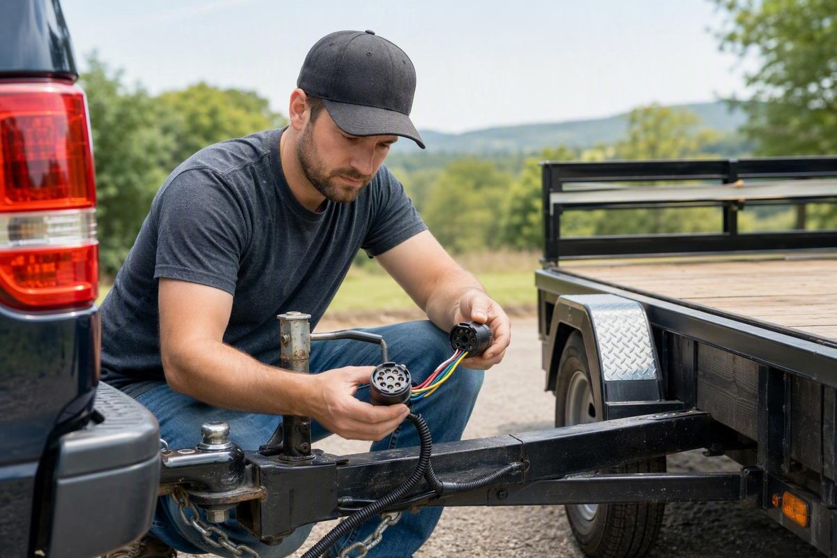
A reliable 7-way trailer installation starts with circuit function—not an assumed wire color, pin number, or online connector picture.
This guide covers the common North American 7-way flat-blade connection and provides circuit schematics for electric brakes, grounding, auxiliary power, and a breakaway system. It does not present one terminal-position pinout as universal. Exact terminal positions must come from the markings or installation diagram for the specific plug and socket being wired.
Use this sequence:
- Confirm the connector family.
- Identify whether a diagram shows the vehicle socket or trailer plug.
- Confirm whether the view is the mating face or rear wire-entry side.
- Test every tow-vehicle socket terminal by function.
- Transfer those functions to the labeled terminals of the specific trailer plug.
- Route brake output and ground to every applicable brake assembly.
- Install and test the breakaway system according to its instructions.
- Verify actual brake engagement before towing.
Wire color is a useful clue. It is not proof.
What a 7-Way Connection Carries—and Which Connector This Guide Covers
This guide applies to the common North American 7-way flat-blade connector, also called a 7-way RV blade or 7-pole blade connector. This connector is widely used on newer trucks and SUVs and on brake-equipped RV, cargo, utility, and equipment trailers.
It does not cover the less common 7-way round-pin family. Flat-blade and round-pin connectors have different contact designs, so a layout for one must not be assigned to the other by assumption. Connector and wire colors can also vary by manufacturer, which is why the individual circuits should be verified with a tester rather than identified solely by color (etrailer’s connector and wiring overview).
A typical brake-equipped 7-way connection carries seven functions:
- Ground
- Running, tail, and marker lights
- Left turn and left brake lamp
- Right turn and right brake lamp
- Electric-brake controller output
- 12-volt auxiliary power
- Reverse lights
The basic function flow is:
TOW VEHICLE                                          TRAILER

Vehicle ground  ── Vehicle socket ── Trailer plug ── Ground network
Running lights  ── Vehicle socket ── Trailer plug ── Tail/marker lamps
Left turn/brake ── Vehicle socket ── Trailer plug ── Left rear lamp
Right turn/brake── Vehicle socket ── Trailer plug ── Right rear lamp
Brake controller── Vehicle socket ── Trailer plug ── Electric brakes
Auxiliary power ── Vehicle socket ── Trailer plug ── Supported 12 V loads
Reverse signal  ── Vehicle socket ── Trailer plug ── Reverse lamps/load
This is a circuit schematic, not a terminal-position diagram. It shows what must connect without claiming that every connector uses the same printed numbers, colors, or diagram orientation.
The left and right turn/brake circuits operate the trailer’s rear lamps. A left turn command flashes the left circuit. When the service brakes are applied without a turn signal, the left and right circuits operate their respective stop lamps.
The electric-brake circuit is separate. It carries output from the tow vehicle’s brake controller to the trailer’s electric brake assemblies. It is not the trailer stop-lamp circuit and should not be treated as constant auxiliary power.
That distinction prevents three common errors:
- Connecting the electric brakes to a stop-lamp wire
- Treating brake-controller output as an auxiliary supply
- Assuming that working brake lamps prove that the electric brakes work
Before making connections, record the following:
- Plug manufacturer and part number
- Socket manufacturer and part number, if available
- Connector family
- Molded terminal labels
- Locating notch, key, or lid-hinge orientation
- Whether the supplied diagram shows the mating face or wire-entry side
- Existing junction-box labels
- Visible wire colors, used only as secondary information
The exact diagram may be molded into the connector, printed on its packaging, included in an installation sheet, or published against the exact part number. Also consult the tow vehicle, brake controller, trailer, and breakaway-kit instructions.
If the connector family or viewing direction cannot be positively identified, stop rather than guessing.
The Typical 7-Way Wire-Color Chart
The table below shows a commonly published traditional color convention. These colors are typical, not universal. An alternate RV arrangement can carry the same broad functions with different insulation colors, so colors on opposite sides of a junction box may not match even when the circuits do (Mechanical Elements’ comparison of traditional and RV wiring).
| Circuit function | Typical traditional color | Signal behavior | Typical trailer destination |
|---|---|---|---|
| Ground | White | Return path for connected loads | Ground bus, frame bond where used, lamps, brakes, accessories |
| Running, tail, and marker lights | Brown | Switched with the vehicle’s parking or headlamps | Tail lamps, marker lamps, clearance lamps, license-plate lamp |
| Left turn/brake lamp | Yellow | Flashes for left turn; operates as the left stop-lamp feed | Left rear combination lamp |
| Right turn/brake lamp | Green | Flashes for right turn; operates as the right stop-lamp feed | Right rear combination lamp |
| Electric-brake output | Blue | Varies with brake-controller command | Brake feed to applicable electric brake assemblies |
| 12-volt auxiliary power | Black or red | May be constant, switched, relay-controlled, or vehicle-managed | Supported accessories or breakaway charging input |
| Reverse lights | Purple or gray | Switched under the vehicle’s reverse operating condition | Trailer reverse lamps or another documented reverse-controlled load |
Read the table from left to right: identify the circuit function first, then consider color as supporting information.
Why color matching fails
Traditional and RV-style harness conventions can assign different colors to the same function. Repairs and owner modifications introduce further variation.
For example, a brown incoming conductor might be a verified running-light circuit, while the running-light post in an RV-style junction box is connected to a different-colored outgoing wire. Joining brown to brown without checking the terminal labels could cross two unrelated circuits.
Use this chain instead:
Verified tow-vehicle function
              ↓
Identified vehicle-socket terminal
              ↓
Corresponding labeled trailer-plug terminal
              ↓
Labeled junction-box function
              ↓
Verified trailer destination
At each transition, match function to function.
What each signal should do
Ground completes the return path. It is not a switched power source.
Running lights operate with the tow vehicle’s lighting controls. They feed the trailer’s tail, marker, clearance, and related lamps—not the auxiliary system.
Left and right turn/brake circuits are separate so each side can flash independently. The vehicle’s trailer wiring system also uses them as the respective stop-lamp feeds.
Brake-controller output is commanded by the controller. Its behavior can change with manual-control position, controller adjustment, braking input, or controller design.
Auxiliary power is a separate supply. Its availability depends on the tow vehicle and installation; it must not be assumed to be continuously energized.
Reverse power is a separate switched function. Its terminal position should be determined from testing and the actual connector documentation, not from a generic picture.
When inherited wiring is uncertain, test and label each conductor before making permanent connections.
How to Read Plug and Socket Views Without Reversing the Wiring
A vehicle socket and trailer plug connect face to face. Their contact arrangements therefore appear mirrored when each is viewed from its mating face.
Looking at the rear wire-entry side creates another apparent reversal. That produces four distinct views:
1. VEHICLE SOCKET — MATING FACE
   The socket face visible at the rear of the tow vehicle.

2. VEHICLE SOCKET — WIRE-ENTRY SIDE
   The rear of the socket where vehicle conductors terminate.

3. TRAILER PLUG — MATING FACE
   The face inserted into the vehicle socket.

4. TRAILER PLUG — WIRE-ENTRY SIDE
   The rear of the plug where trailer conductors terminate.
A usable connector drawing must identify all of the following:
- Vehicle socket or trailer plug
- Mating face or wire-entry side
- Locating notch, key, lid hinge, or another defined index
- Terminal function labels
- Connector or part number to which the drawing applies
Use this orientation worksheet when comparing the actual connector with its diagram:
| Item | Connector documentation | Actual connector |
|---|---|---|
| Connector type | ||
| Manufacturer | ||
| Part number | ||
| Vehicle socket or trailer plug | ||
| Mating face or wire-entry side | ||
| Notch/key/hinge position | ||
| Molded terminal labels |
Use the notch, not an assumed pin number
Printed pin numbers are not consistent across every plug and socket, and some connectors omit them. A locating notch or key provides a physical orientation reference.
Use this process:
- Find the exact diagram for the connector or part number.
- Hold the connector in the orientation shown.
- Locate the specified notch, key, hinge, or index.
- Confirm whether the diagram shows the mating face or wire-entry side.
- Read the function labels molded beside the terminals.
- Transfer the electrically verified socket functions to the corresponding plug functions.
- Use continuity testing if the plug’s internal connection path is not apparent.
Do not mentally flip an unidentified diagram. Mark the index feature and redraw the view if necessary.
Stop and check: If a diagram does not explicitly identify vehicle socket or trailer plug and mating face or wire-entry side, do not wire from it.
Auxiliary power could reach an unintended load, lighting circuits could be exchanged, or controller output could be routed somewhere other than the brakes. Incorrect wiring can damage electrical components, so resolve the orientation before applying power.
Electric-Brake Wiring From the Controller to Every Brake Assembly
The typical brake circuit begins at the tow vehicle’s brake controller and continues through the connector to every applicable electric brake assembly:
Tow-vehicle power and braking inputs
                   │
                   ▼
            Brake controller
                   │
          commanded brake output
                   │
                   ▼
          Vehicle 7-way socket
                   │
                   ▼
           Trailer 7-way plug
                   │
                   ▼
       Trailer junction or main harness
                   │
                   ▼
       Branches to every electric brake
Blue commonly identifies the brake-output circuit in the traditional color convention. It does not identify the vehicle brake-switch input to the controller, and it is not the constant or vehicle-managed auxiliary-power feed.
A powered or illuminated controller does not prove that output reaches the trailer brakes. The output must be checked at the vehicle socket and downstream through the trailer, followed by a controlled operational test.
Single braked axle
A single braked axle normally has one electric brake assembly at each wheel. Both need a brake-output path and a return path:
TRAILER PLUG / JUNCTION

Brake-controller output
          │
          ├──────────────────────► Left brake assembly
          │
          └──────────────────────► Right brake assembly

Ground return
          │
          ├──────────────────────► Left brake assembly
          │
          └──────────────────────► Right brake assembly
This schematic shows circuit relationships, not universal connector positions.
Route it away from sharp edges, moving suspension components, heat, and likely impact areas. Connections and strain relief should suit the conductor, connector, environment, and expected movement.
Tandem braked axles
When both axles have electric brakes, the output and ground networks must reach all applicable assemblies:
TRAILER PLUG / JUNCTION

Brake output
    │
    ├────────► Front-left brake
    ├────────► Front-right brake
    ├────────► Rear-left brake
    └────────► Rear-right brake

Ground return
    │
    ├────────► Front-left brake
    ├────────► Front-right brake
    ├────────► Rear-left brake
    └────────► Rear-right brake
Selecting brake and ground wire size
There is no responsible universal wire gauge for every brake-equipped trailer. Selection depends on:
- The number and electrical load of the brake assemblies
- Total feed and return length
- Acceptable voltage drop
- Conductor material and temperature rating
- Routing and bundling
- Terminal and connector capacity
- Requirements from the trailer, brake, and controller manufacturers
The return path must be able to carry the brake load. A substantial brake-output conductor cannot compensate for a weak ground connection through painted, rusty, loose, or uncertain mechanical interfaces.
A staged brake-circuit test
After wiring the brake branches:
- Verify controller output at the tow-vehicle socket under manual activation.
- Connect the trailer.
- Check for output after the trailer plug.
- Check downstream of the junction or main splice.
- Check the feed and ground at each brake branch.
- Confirm actual engagement according to the brake and controller instructions.
A controller display may indicate power or connection status, but it cannot prove that every conductor, splice, ground, or brake assembly is operating.
Grounding the Plug, Frame, Lights, and Brakes
White is the typical ground color in the traditional scheme, but a white conductor in an inherited harness must still be verified.
A brake-equipped trailer needs a deliberate ground connection through the plug and socket. Do not use the hitch ball as the sole electrical return. The ground conductor must be suitable for the connected load, and frame grounds should terminate securely to clean, bare metal (AJ’s truck-to-trailer grounding guidance).
That makes it unsuitable as the only return path.
Show the ground beside the brake feed
Ground is half of every circuit:
TOW VEHICLE                                      TRAILER

Brake controller ── brake-output terminal ───────┬── Brake A
                                                  ├── Brake B
                                                  ├── Brake C, if fitted
                                                  └── Brake D, if fitted

Vehicle ground ─── ground terminal ──────────────┬── Brake A return
                                                  ├── Brake B return
                                                  ├── Brake C return
                                                  ├── Brake D return
                                                  ├── Lamp returns
                                                  └── Ground bus/frame bond
The main ground path may have to carry the combined return load of brakes, marker lamps, stop lamps, reverse lamps, and supported auxiliary equipment operating at the same time. Size and configure it for the actual installation.
Frame grounds
Where the trailer design uses a frame bond:
- Select sound metal suitable for the connection.
- Remove paint, rust, dirt, and contamination from the electrical contact area.
- Use suitable hardware that can remain secure.
- Route and support the conductor so movement does not pull on the terminal.
- Protect the completed area from renewed corrosion without insulating the contact.
- Include the bond in routine inspection.
A fastener installed over paint can look tight while providing a poor electrical path. Corroded ring terminals, loose hardware, and damaged metal can produce the same problem.
Whether the frame forms part of the return path or serves as an additional bond, the plug ground should remain traceable.
Ground-fault symptoms
A weak ground can cause:
- Dim or unstable lamps
- One lamp glowing when another circuit is selected
- Lights working individually but failing in combination
- Brake operation affecting marker lights
- Marker lights affecting stop or turn lamps
- Intermittent operation as the trailer moves
- Apparent cross-feeding between circuits
A failure that appears only under combined load is a useful clue. If the lights work separately but malfunction when the brakes and marker lights operate together, inspect the truck-to-trailer ground and common junctions before reassigning wires.
A complete-looking path without meaningful load does not establish that the connection will perform correctly when the brakes and lamps operate.
Auxiliary Power, Reverse Lights, and the Breakaway Circuit
The remaining circuits have distinct purposes:
- Brown running-light circuit: switched lighting feed
- Blue brake-output circuit: controller-commanded brake feed
- Black or red auxiliary circuit: separate 12-volt supply
- Purple or gray reverse circuit: switched reverse signal
Do not bridge them because one function is unused.
Auxiliary power
Depending on the trailer and tow vehicle, the auxiliary circuit may support:
- A breakaway-battery charging input
- Interior trailer lighting
- A supported trailer battery system
- Relays or other documented accessories
Its behavior is vehicle-specific. It may be continuously available, ignition-switched, relay-controlled, or enabled only under certain vehicle or trailer-detection conditions.
Test it under the conditions specified by the vehicle manufacturer.
Use the vehicle, controller, wiring-kit, and accessory instructions rather than copying a universal fuse or breaker rating.
Reverse lights
The reverse circuit is a separate switched function. It may operate trailer reverse lamps or another specifically documented reverse-controlled device.
Do not assume that:
- The center terminal is always reverse.
- Purple or gray always identifies reverse.
- An unused-looking terminal can be reassigned without documentation.
- A drawing for another connector family applies.
Identify the reverse function at the vehicle socket under the vehicle manufacturer’s required operating conditions. Prevent vehicle movement and use an appropriate helper or testing procedure. Transfer the verified function to the reverse-labeled terminal of the actual trailer plug.
Conceptual breakaway schematic
A typical breakaway system provides a separate emergency path intended to apply the trailer brakes if the trailer separates from the tow vehicle:
NORMAL CHARGING PATH

Vehicle auxiliary supply
          │
          ▼
Trailer 7-way plug
          │
          ▼
Breakaway charging input
          │
          ▼
Breakaway battery
          │
          └──────── Ground return


EMERGENCY ACTUATION PATH

Breakaway battery positive
          │
          ▼
Breakaway pull switch
          │
          ▼
Trailer brake feed
          │
          ├────────► Brake assembly 1
          ├────────► Brake assembly 2
          ├────────► Additional brakes, if fitted
          │
          ▼
Ground return to breakaway battery
This is a conceptual circuit, not a replacement for the kit’s instructions. A particular kit may include a charger, test indicator, battery enclosure, dedicated leads, or other components. The broad arrangement keeps auxiliary charging, controller output, lighting, and breakaway wiring functionally distinct (Johnson Trailer Parts’ 7-way and breakaway overview).
Follow the exact kit instructions for:
- Battery and switch mounting
- Pull-cable routing
- Charging-input connection
- Ground and brake-feed connections
- Battery testing
- Switch activation testing
- Returning the system to its ready state
Check the brake and breakaway requirements applicable to the trailer’s configuration, use, weight class, and operating jurisdiction. Do not rely on a generalized legal threshold.
Leaving functions unused
If the trailer has no reverse lamps or supported auxiliary equipment, those functions may generally remain unconnected.
Safely isolate and document the unused conductor or terminal. Do not relocate the other functions merely to occupy an empty terminal. Preserving the normal assignments makes future testing and service easier.
Function-First Installation and Circuit Verification
Begin at the tow-vehicle socket. Until its functions are verified, the trailer plug has no dependable reference.
Tools and materials
Gather equipment appropriate to the connector and installation:
- Connector-specific installation diagram
- Tow-vehicle documentation
- Brake-controller instructions
- Breakaway-kit instructions
- 7-way plug tester or circuit tester
- Multimeter or suitable test light
- Wire cutters and stripping tools
- Correct terminal or connection tools
- Suitable terminals, connectors, fasteners, and junction hardware
- Specified insulation or sealing materials
- Loom, conduit, clips, or clamps
- Connector mounting hardware
- Labels or a circuit worksheet
Do not impose one strip length, crimp style, torque, or sealing method on every product. Screw-terminal plugs, molded leads, sealed crimps, and stud-type junction boxes require different preparation.
Follow the exact connector instructions for conductor preparation, terminal orientation, crimping or screw termination, sealing, strain relief, and mounting.
Step 1: Inspect before testing
Inspect the vehicle socket for:
- Bent or displaced contacts
- Corrosion or contamination
- Water entry
- A cracked housing
- Loose mounting
- A damaged lid or seal
- Unsupported rear wiring
- Unexplained splices or modifications
Repair visible damage before relying on test results from the connector.
Step 2: Establish a verified ground
Identify the socket ground from the connector documentation or molded label, then verify it against a known vehicle ground using an appropriate test method.
Do not use an uncertain socket terminal as the reference for identifying all the others. A defective reference ground can make every result misleading.
Record the results:
| Connector reference | Verified function | Test condition | Visible wire color | Notes |
|---|---|---|---|---|
| Notch-relative position or molded label | Ground | Vehicle off | ||
| Running lights | Parking lights on | |||
| Left turn/brake | Left signal, then brake | |||
| Right turn/brake | Right signal, then brake | |||
| Reverse | Required reverse condition | |||
| Auxiliary power | Conditions specified by vehicle maker | |||
| Brake output | Controller manual control |
Step 3: Identify the lighting functions
Using the verified ground reference:
- Turn on the running or parking lights.
- Identify and record the running-light terminal.
- Turn the lights off and confirm that the signal changes.
- Operate the left turn signal and identify the pulsing left circuit.
- Apply the service brake as appropriate and confirm its stop-lamp role.
- Repeat for the right turn/brake circuit.
Record each result immediately. Testing one function at a time reduces confusion between a pulsing signal, a crossed circuit, and an unstable ground.
Step 4: Identify reverse and auxiliary power
Test the reverse circuit only with the vehicle secured against movement and under the operating procedure specified by its manufacturer.
Check auxiliary power under the relevant documented conditions. These may include ignition state, engine operation, trailer connection, or an enabled towing mode. Record what the circuit actually does rather than labeling it constant or switched from assumption.
Step 5: Verify brake-controller output
Use the controller’s manual control while monitoring the candidate brake-output terminal.
Do not confuse:
- The vehicle stop-lamp signal used as a controller input
- The left and right trailer stop/turn outputs
- The controller’s output to the electric brakes
All relate to braking, but they perform different jobs.
Step 6: Transfer functions to the trailer plug
After documenting every vehicle-socket function:
- Open the specific trailer plug.
- Identify its locating notch or key.
- Confirm whether its diagram shows the mating face or wire-entry side.
- Read the molded terminal labels.
- Match each verified function to its corresponding labeled terminal.
- Ignore insulation color when it conflicts with verified function.
- Label nonstandard colors inside the plug or junction box.
- Terminate each conductor according to the connector instructions.
- Apply strain relief to the cable jacket as designed.
- Seal and mount the assembly as specified.
Before closing the plug, review every connection by function: “ground to ground,” “controller output to brake,” “running lights to running lights,” and so forth.
Step 7: Protect and document the installation
Secure the connector and harness so they do not dangle or drag. Protect wiring at frame openings, axle crossings, flex points, and exposed underside runs. Retain the completed worksheet with the trailer records or in a protected location near the junction box.
Do not increase a fuse or breaker rating merely because the existing protection repeatedly opens. Diagnose the fault, overload, damaged conductor, or incorrect circuit assignment.
If the circuits cannot be identified positively, documentation conflicts with measured behavior, or unexplained modifications remain, have a qualified trailer or automotive electrical professional inspect the installation. Improper wiring can damage the vehicle, controller, connector, or trailer equipment.
Troubleshooting and the Pre-Tow Brake Test
Troubleshoot in the direction power travels:
Tow vehicle
    ↓
Vehicle socket output
    ↓
Plug-and-socket contact
    ↓
Trailer junction or main splice
    ↓
Ground and main harness
    ↓
Circuit branches
    ↓
Individual load connection
    ↓
Lamp, accessory, or brake assembly
This sequence prevents unnecessary trailer disassembly when the fault is at the vehicle socket—and prevents blaming the controller when output is lost farther downstream.
Symptom-to-cause guide
| Symptom | Areas to inspect | Useful next check |
|---|---|---|
| No trailer brakes | Controller output, socket assignment, plug contact, brake feed, ground, junctions, branches, brake assemblies | Activate the manual control and trace output downstream |
| Intermittent braking | Loose plug, corrosion, strained cable, weak ground, damaged axle wiring, loose splice | Inspect movement, flex, and impact points while monitoring the circuit |
| Dim or crossed lights | Incorrect assignments, weak ground, corrosion, damaged harness | Verify socket functions and test under combined load |
| Several functions fail together | Main ground, connector damage, common splice, main harness | Inspect shared ground and junction points |
| Protection device opens | Pinched or bare wire, water-contaminated connector, crossed circuit, failed load, overload | Isolate sections methodically; do not install a larger device |
| No auxiliary power | Vehicle-controlled feed, protection device, relay, configuration, connector fault | Test under the vehicle maker’s specified conditions |
| No reverse function | Incorrect vehicle state, crossed terminal, damaged lead, unassigned circuit | Verify reverse output at the vehicle socket first |
| Controller is powered but brakes do not engage | Missing output, open trailer connection, weak ground, damaged brake conductor, brake fault | Test progressively from the socket to every brake branch |
Poor grounds, corrosion, pinched or cut conductors, bare wiring, water exposure, and incorrect circuit assignments can affect trailer lights and brakes. Secure mounting and protected routing reduce avoidable connector and harness damage.
When lights work but brakes do not
Working lights prove only that some lighting circuits and part of the return path operate. They do not prove that:
- The controller produces brake output
- The socket brake terminal is assigned correctly
- The plug contacts that terminal
- The main brake conductor is continuous
- The brake ground is adequate
- Every axle branch is connected
- The brake assemblies engage
Start with manual controller activation at the vehicle socket. If output is present, continue downstream:
- Socket contact
- Mated trailer plug
- Plug wire-entry termination
- Junction-box brake terminal
- Main brake conductor
- Axle branch connections
- Individual brake leads
- Ground return
- Brake assemblies
Do not replace brake assemblies merely because output exists at the socket. A failed plug termination, junction, conductor, or ground can interrupt every brake.
When multiple functions interfere
If marker lights, turn signals, and brakes operate separately but interfere when combined, inspect the common return path:
- Vehicle socket ground
- Trailer plug ground terminal
- Main trailer ground conductor
- Junction-box ground point
- Frame bond, if used
- Lamp and brake returns
- Corroded or loose terminals
Do not treat hitch-ball contact as proof of a dependable ground.
When a protection device opens repeatedly
Inspect for:
- Pinched cable
- Bare copper touching the frame
- Water or corrosion between connector terminals
- Crossed auxiliary-power wiring
- Damaged insulation at clamps or frame openings
- Failed loads or splices
- More load than the circuit was designed to supply
Pre-tow electrical checklist
Before towing, verify:
- [ ] The plug seats fully and the socket retainer holds it.
- [ ] The cable has enough movement for turns but cannot drag.
- [ ] Running, tail, marker, and clearance lamps work.
- [ ] The left turn and left brake-lamp functions work.
- [ ] The right turn and right brake-lamp functions work.
- [ ] Reverse lights work where fitted.
- [ ] Auxiliary voltage is present only where and when expected.
- [ ] No circuit causes unrelated lamps to glow or dim.
- [ ] The socket, plug, and junction box are securely mounted.
- [ ] The harness is protected from sharp edges, heat, moving parts, and road damage.
- [ ] The brake controller produces output under manual activation.
- [ ] All applicable trailer brakes engage.
- [ ] The breakaway system passes its manufacturer’s test.
- [ ] The breakaway switch and cable are restored to their ready state.
Confirm actual brake engagement
Use the controller’s manual control during a controlled low-speed check in a suitable area. The purpose is to verify that the trailer brakes actually engage, not merely that the controller powers up or produces a socket signal. Socket-first testing followed by manual brake activation is also reflected in JACO’s diagnostic sequence (trailer wiring diagnostic guide).
Adjust the controller only according to its instructions and the requirements of the tow vehicle and trailer. If braking is absent, erratic, unbalanced, or uncertain, do not treat the trailer as ready to tow.
Escalate the work to a qualified professional when:
- Socket functions cannot be positively identified
- Documentation conflicts with measured behavior
- Protection devices repeatedly open
- Conductors or terminals overheat
- Water damage is extensive
- Unexplained modifications remain
- Brake engagement is uncertain
- A vehicle-specific controller installation is required
The durable method is always the same: identify the connector family and viewing side, verify every vehicle circuit, match functions rather than colors, provide brake output and a dependable return path to every applicable wheel, and test actual engagement before towing. The color chart is only a starting point; the connector markings, exact component instructions, vehicle documentation, and measured behavior control the final installation.
Frequently Asked Questions
Which wire controls the electric brakes on a typical 7-way trailer plug?
In the commonly published traditional color convention, the blue wire carries brake-controller output to the electric brakes. It is separate from the yellow and green stop/turn lamp circuits and from the black or red auxiliary-power circuit.
Treat blue as a clue, not proof. Verify controller output at the vehicle socket with the controller’s manual control, then connect that verified function to the brake-output terminal identified on the specific trailer plug.
Can I wire a 7-way connector by matching wire colors?
No. Traditional, RV-style, manufacturer-specific, repaired, and owner-modified harnesses may use different colors.
Identify each vehicle-socket terminal electrically, record its function, and connect it to the matching function label on the trailer plug. This is particularly important where a traditional-colored cable enters an RV-style junction box.
Why does the trailer-plug diagram look reversed from the vehicle socket?
The vehicle socket and trailer plug appear mirrored when viewed from their corresponding mating faces because they connect face to face. Looking at the rear wire-entry side reverses the apparent layout again.
Use the locating notch or another specified index. Confirm the connector type and viewing side before assigning any terminal.
Can the reverse-light or auxiliary-power terminal be left unused?
Generally, yes. If the trailer does not use reverse lights or auxiliary power, the corresponding circuit can remain safely isolated and unconnected.
Do not move the other functions into the unused position. Preserve the documented assignments for compatibility and future service.
Why do my trailer lights fail when the brakes and marker lights are on together?
That pattern can indicate a weak or missing truck-to-trailer ground. One circuit may work by itself, but the return path may become inadequate when several loads operate together.
Inspect the vehicle socket ground, trailer plug terminal, main ground conductor, junction-box connection, frame bond where used, and individual load returns. Also check for corrosion, loose hardware, paint beneath ground terminals, and damaged conductors.