
22 min read ·
Identify Your 7-Way Connection Before You Touch the Wires
Seven contacts do not guarantee the same shape, keying, wiring, functions or diagram view. Identify the family, component side and view before replacing one.
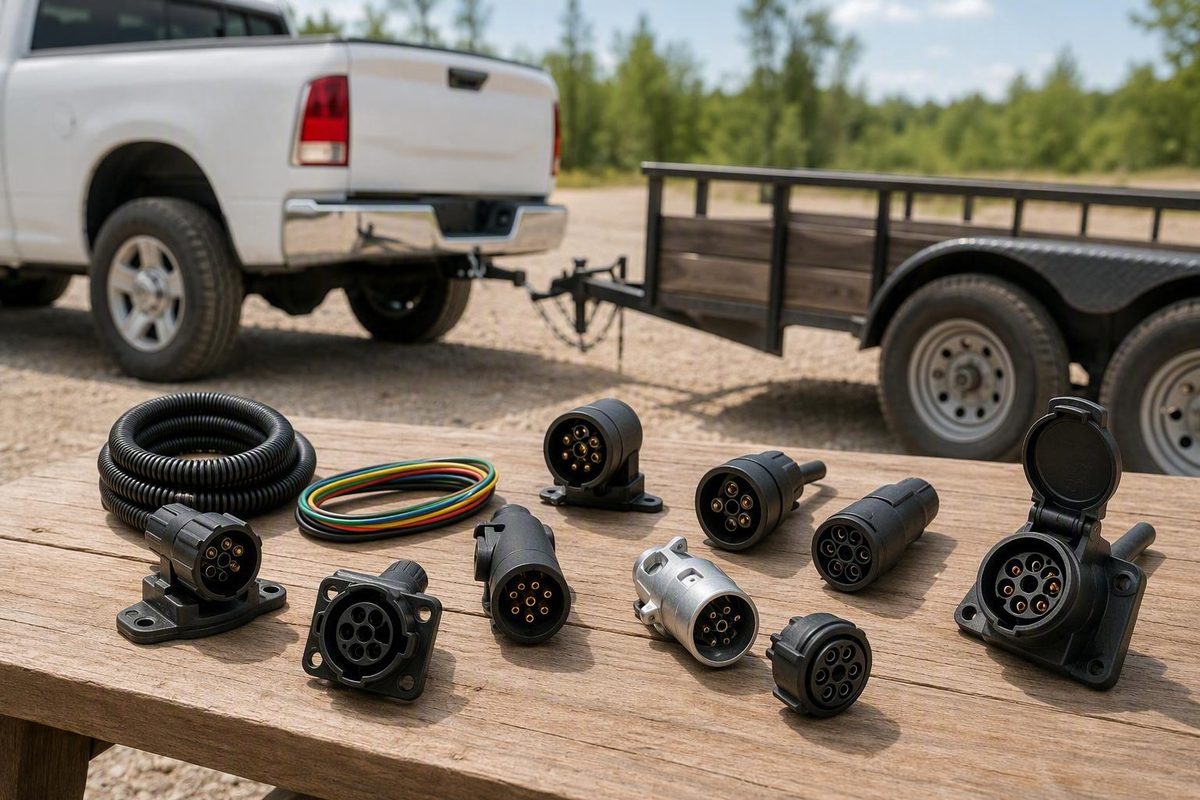
A seven pin trailer connector is not one universal plug with one universal wiring diagram. “Seven-pin” and “seven-way” describe the number of electrical contacts—not their shape, physical keying, terminal arrangement, circuit functions, wire colors, or whether the diagram shows the trailer plug or vehicle socket.
That distinction matters when replacing a damaged connector, installing a towing harness, diagnosing a fault, or choosing an adapter. A connector may fit physically while routing the wrong signals. A correct diagram may appear reversed because it shows the wire-entry side instead of the contact face. A familiar wire color may serve a different function under another convention.
Use this sequence:
- Identify the connector family and component side.
- Confirm the diagram’s viewing orientation.
- Verify each conductor by function.
- Choose parts that preserve the required circuits.
- Test every fitted function before towing.
This guide focuses on identification, compatibility, product selection, and bounded troubleshooting. It is not a universal pinout or a substitute for connector-specific instructions, vehicle documentation, brake-controller procedures, circuit-protection requirements, or breakaway-system instructions.
Why “seven pin” does not identify one universal connector
At least three substantially different connector families are commonly described as seven-pin or seven-way:
- North American RV blade or flat-pin connectors. These usually have a round outer body but flat blade contacts.
- True round-pin connectors. These use cylindrical contacts and appear in some commercial, agricultural, and heavy-equipment applications.
- European ISO 1724 seven-pin connectors. These use a different physical and electrical arrangement intended primarily for basic trailer lighting.
The housing shape does not establish the contact type. A listing may call an RV-style connector “round” because the shell is round even though its contacts are flat blades. Inspect the electrical contacts rather than relying on the product title.
Some North American RV and utility blade arrangements share terminal functions while using different wire-color conventions. That limited compatibility does not automatically extend to true round-pin equipment or ISO 1724 systems. CURT’s guide distinguishes round-prong, RV blade SAE, and traditional RV blade arrangements and advises checking the connector type and actual wiring before making connections (CURT trailer-wiring guide).
A practical identification checklist
Before buying a replacement or opening the housing, inspect:
- Contact geometry: Are the contacts flat blades or round pins?
- Contact arrangement: How are the outer contacts positioned around the center?
- Keyway and indexing: Where are the locating notch, latch, cover, and other polarizing features?
- Housing markings: Look for a standard, manufacturer, part number, voltage designation, or terminal labels.
- Component side: Is the damaged part attached to the trailer or vehicle?
- Mating half: Photograph the opposite connector and confirm that its contacts and keying correspond.
- Supplied diagram: Does it identify the connector family, terminal functions, component side, and viewing direction?
- Vehicle documentation: Is there an OEM tow package, a USCAR interface, an aftermarket harness, or evidence of previous modification?
- Functions present: Does the trailer use electric brakes, reverse lights, auxiliary power, a battery feed, or only road lighting?
Treat phrases such as “round trailer plug,” “seven-prong,” and “RV-style” as search terms, not compatibility specifications.
If the connector family cannot be identified confidently, stop. Obtain documentation for the exact connector, have the installed circuits identified with suitable test equipment, or consult a qualified trailer-wiring or automotive technician. Do not use trial and error on unknown brake-output or battery-power conductors.
Plug, socket, and viewpoint: identify the side before buying or wiring
In customary trailer-wiring terminology:
- The trailer-side component is the plug.
- The tow-vehicle component is the socket or receptacle.
Product listings do not always use these terms consistently. Verify the detailed description and photographs rather than assuming that “trailer connector” means trailer-side.
Buyers Products identifies TC1770B and TC1770P as truck-side, seven-pin RV-flat receptacles. The manufacturer offers bolt-on and twist-lock versions intended to connect to an OEM tow-package harness, but the page does not provide a complete vehicle-fitment list (Buyers Products seven-way flat-pin receptacles).
Del City item 73725 is different: it is described as a trailer-side metal plug with seven round-pin contacts. It is an example of a true round-pin product, not an RV blade plug (Del City seven-way round-pin plug).
TowSmart model 1430 is also a trailer-end replacement. It plugs into a vehicle socket and splices into trailer wiring, but its retail page does not supply a complete pinout or establish universal compatibility (TowSmart model 1430 trailer-end connector).
Why diagram orientation matters
A connector diagram may depict any of four views:
- Vehicle socket viewed at the contact face
- Vehicle socket viewed from the wire-entry side
- Trailer plug viewed at the contact face
- Trailer plug viewed from the wire-entry side
Plug and socket illustrations can also differ according to how the drawing is presented. A keyway shown at the top is not enough unless the diagram identifies both the component and the viewing side.
Before applying a diagram, answer:
- Which connector family does it depict?
- Is it the trailer plug or vehicle socket?
- Is the view from the mating face or the wire-entry side?
Do not transfer terminal positions if any of those answers is missing.
A safer pre-purchase sequence
Before ordering a replacement:
- Photograph the vehicle socket with its cover open.
- Photograph the trailer plug’s contact face.
- Photograph labels and the rear terminal arrangement if it can be exposed without disturbing unknown wiring.
- Note the keyway, latch position, center contact, and contact shape.
- Record whether the damaged component is on the trailer or tow vehicle.
- Label known functions connected to the old terminals.
- Compare those functions—not just wire colors—with the replacement instructions.
- Verify cable diameter, cable entry, mounting method, strain relief, and available clearance.
A similar shell and a count of seven contacts are insufficient. The replacement must mate mechanically and reproduce the required electrical functions in the correct terminal positions.
What the seven circuits can do, by connector family
A function matrix is more useful than a purported universal pinout. It shows what each family can commonly support without implying that every terminal occupies the same physical position.
| Circuit or function | North American seven-way RV-style system | ISO 1724 seven-pin example | Qualification |
|---|---|---|---|
| Ground | Common | Common | Position and color still require verification |
| Tail or running lights | Common combined running-light circuit | Divided between left and right rear-light circuits | The arrangements differ |
| Left turn | Usually combined with left stop | Separate indicator circuit | Combined and separate systems are not automatically interchangeable |
| Right turn | Usually combined with right stop | Separate indicator circuit | Conversion may be needed between signal arrangements |
| Brake lights | Carried through combined left/right circuits | Separate brake-light circuit | Depends on connector family |
| Electric-brake output | Commonly supported | Not part of the cited ISO 1724 layout | Requires compatible wiring and a brake controller |
| Auxiliary 12-volt power | Commonly supported | Not part of the cited ISO layout | Power, charging, and auxiliary use are not synonymous |
| Reverse lights | Commonly supported, but not fitted to every trailer | Not part of the cited ISO layout | Confirm whether the trailer uses them |
| Rear fog light | Not in the common North American function set | Included | Do not repurpose it from a North American chart |
Common North American seven-way functions
A common North American RV-style system can carry:
- Ground
- Tail or running lights
- Combined left turn and stop
- Combined right turn and stop
- Electric trailer-brake output
- Auxiliary 12-volt power
- Reverse lights
These are common functions, not a universal color code or terminal-position chart. Electric trailer brakes also require compatible tow-vehicle wiring and an appropriate brake controller; installing a seven-way socket alone does not create controlled brake output (etrailer seven-way wiring overview).
Interpret “auxiliary power” narrowly. Depending on the documented installation, a powered terminal may maintain a trailer battery or operate selected equipment.
Likewise, a generically labeled seventh contact is not universally “backup,” “battery,” “charge,” or “auxiliary.” Determine what the vehicle supplies and what the trailer expects.
ISO 1724 seven-pin functions
The cited ISO 1724 example assigns the seven circuits to:
- Left indicator
- Rear fog light
- Ground
- Right indicator
- Right rear, marker, and number-plate lighting
- Brake lights
- Left rear and marker lighting
This is a basic lighting arrangement, not a North American RV pinout. The source recommends a 13-pin system when reverse lights, constant power, or caravan-related electrical functions are required (TRALERT ISO 1724 seven-pin scheme).
That difference prevents casual transfer of function labels between connector families. Where a North American arrangement may provide electric-brake output and auxiliary power, the cited ISO arrangement uses rear fog and divided rear-light circuits.
One product-specific SAE example
Waytek part 37647 illustrates how narrowly a color chart must be applied. The seller describes it as a six-foot, seven-circuit SAE-wired assembly with:
- 12 AWG blue: electric brakes
- 10 AWG white: common ground
- 14 AWG red: 12 VDC hot or charger
- 14 AWG brown: tail or marker lights
- 14 AWG green: right turn
- 14 AWG yellow: left turn
- 10 AWG black: auxiliary or backup
Those gauges and colors apply to that assembly—not to all seven-way connectors. Even the product’s combined “auxiliary/backup” description does not determine which function a particular installation uses (Waytek part 37647 specifications).
Use the instructions supplied with the exact connector or harness. A product-specific chart is evidence for that product, not permission to generalize its colors or terminal numbers.
Verify circuits by function—not insulation color
Trailer wiring charts conflict because they describe different connector families, conventions, product designs, and diagram orientations. SAE-style wiring, RV conventions, traditional utility wiring, commercial round-pin systems, ISO 1724 connectors, and molded harnesses may assign different colors to comparable functions.
Color is therefore a secondary clue. Verified circuit function is the controlling reference.
White frequently appears as ground in North American examples, but it is not a universal ground color across every seven-pin system, imported trailer, custom harness, or previous repair. An earlier installer may also have used whatever conductor was available.
References to gather before connecting anything
Collect as many of these as are available:
- Instructions for the exact replacement connector
- Tow-vehicle owner or service documentation
- Trailer manufacturer wiring information
- Brake-controller instructions
- OEM tow-package or USCAR harness documentation
- Labels inside the existing junction box
- Photographs and notes made before disassembly
- Instructions for the circuit tester or multimeter being used
If two documents disagree, first confirm that they describe the same connector family, component side, and viewing orientation. Do not choose a diagram merely because its colors look familiar.
A bounded verification workflow
This workflow is intentionally not a universal live-probing procedure:
- Record the existing installation. Photograph each terminal, splice, label, and conductor before disconnecting anything.
- Isolate relevant power before making wiring changes. Disconnect vehicle and trailer battery supplies as directed by the applicable documentation; commercial installation guidance specifically calls for both power sources to be disconnected before wiring (RVGUARD installation guide).
- Identify the connector and view. Confirm its family, plug or socket side, keyway position, and whether the diagram shows the contact face or terminal side.
- Label conductors by known function. Use tags such as “ground,” “right turn/stop,” or “brake output,” not merely “white” or “blue.”
- Compare documentation with the installed wiring. Previous repairs may not follow the original convention.
- Use suitable test equipment. Follow the equipment manufacturer’s instructions and the applicable vehicle or trailer procedure.
- Connect one verified function at a time.
- Inspect before restoring power. Look for exposed strands, loose terminals, pinched insulation, unsupported cable, and unintended contact between terminals.
- Test every fitted function before towing.
The available sources do not establish a universal procedure for energized testing, fuse selection, brake adjustment, controller configuration, or breakaway testing. Use the relevant vehicle, controller, axle, trailer, and connector instructions for those tasks.
Why color and viewpoint errors matter
A mirrored diagram or a color-only assumption can route a lighting conductor to electric-brake output, battery power, reverse lights, or another unintended circuit. The result may appear immediately or only when a particular function is activated.
Do not resolve unknown brake, battery-power, charging, or circuit-protection wiring by trial and error. If those conductors cannot be identified confidently, use a qualified trailer-wiring or automotive professional.
Choose a compatible replacement connector or harness
The correct replacement is determined by the complete system, not the contact count.
Compatibility checklist
Verify:
- Contact geometry: Flat RV blades, true round pins, or another format
- Connector family or identified standard
- Component side: Trailer plug or vehicle receptacle
- Mating arrangement
- Keying and latch position
- Terminal-function layout
- Diagram viewpoint
- Cable-entry direction and permitted cable diameter
- Terminal style: Screw, crimp, molded lead, or junction-box connection
- Mounting method: Bolt-on, twist-lock, bracketed, or in-line
- Mounting dimensions and clearance
- Strain relief and cable support
- Required cable length
- Conductor sizes by circuit
- Product-specific electrical ratings
- Documented material or environmental specifications
- OEM tow-package, USCAR, or vehicle-specific compatibility
- Required brakes, reverse, lighting, and auxiliary-power functions
Do not infer electrical capacity or environmental performance from terms such as “heavy duty,” “weather resistant,” or “commercial.” Check the exact manufacturer or seller documentation.
For example, Del City states a 40-amp rating for item 73725. That is the seller-stated rating for that specific round-pin connector, not a general rating for all seven-way products (Del City item 73725).
Choose the appropriate product form
Bare splice-in connector: Useful when the cable is serviceable and only the plug or receptacle is damaged. It requires sufficient conductor length, compatible terminals, suitable cable entry, and effective strain relief.
Molded cable assembly: The plug and a length of cable form one assembly. This reduces exposed terminations at the plug, but the cable length, conductor sizes, color scheme, and remote connection point must suit the installation.
Junction-box cord: A molded trailer plug and cable terminate in a trailer-mounted junction box. Individual trailer circuits can then connect through identified terminals, providing a central inspection and distribution point.
OEM or USCAR-compatible vehicle harness: A vehicle-specific harness may connect a factory tow-package interface to a seven-way receptacle without cutting the main vehicle harness. Fitment, mounting, circuit activation, and terminal functions remain vehicle-specific.
The Buyers Products receptacles illustrate truck-side bolt-on and twist-lock options intended for OEM tow-package wiring, but their product page does not establish a complete fitment list. Confirm the vehicle interface before ordering.
Cable and conductor requirements
Conductor selection must account for:
- Actual circuit load
- Total conductor length
- Permissible voltage drop
- Fuse or circuit-breaker protection
- Terminal capacity
- Brake-system requirements
- Vehicle and trailer instructions
- Routing and installation conditions
A molded harness may use different conductor sizes for different circuits, as the Waytek example does. That is more useful than a listing that says only “seven-wire cable,” but it does not prove suitability for another trailer’s loads or cable length.
Price, temporary stock, reviews, marketplace badges, and sales volume do not establish compatibility or electrical suitability. Base the decision on geometry, function, documentation, ratings, conductor sizes, mounting, and confirmed fitment.
Plan the installation path on the trailer and tow vehicle
Trailer-side replacement and vehicle-side installation are different jobs. Plan them separately, and use connector, vehicle, trailer, and brake-system instructions for the actual work.
Trailer-side replacement
Two common high-level approaches are:
Junction-box installation: A molded plug cable enters a trailer-mounted junction box, where its conductors connect to corresponding trailer circuits using compatible terminals.
Protected splice-in installation: A replacement harness joins the existing trailer wiring through appropriately sized and protected splices. The connection method must suit the conductor, environment, mechanical strain, and applicable instructions; the evidence does not establish one splice method as best for every installation.
For either approach:
- Confirm each conductor by function.
- Use the connector’s intended strain relief.
- Support the cable rather than allowing terminals to carry pulling force.
- Protect wiring from movement, abrasion, moisture, heat, sharp edges, suspension travel, and pinch points.
- Provide enough service length for maintenance without leaving the cable to drag.
Vehicle-side starting points
1. A working seven-way is already installed
If the existing vehicle socket is electrically compatible with the trailer, no conversion may be necessary. Confirm each required function rather than assuming every terminal is active. A socket’s presence does not establish that brake-controller output or auxiliary power has been installed and configured.
2. An OEM or USCAR connection is present
A vehicle-specific harness may connect the factory interface to an RV-style receptacle. This can avoid cutting the main harness, but vehicle fitment, mounting, circuit activation, terminal functions, and brake-controller requirements still need verification.
3. A four-way connector is present
A four-way generally supplies ground and basic road-lighting functions. Changing the physical interface to a seven-way does not create electric-brake output, reverse, or auxiliary-power circuits.
A four-to-seven-way interface can carry the existing lighting functions into a seven-way receptacle. If electric brakes or auxiliary power are required, those circuits must be installed separately under vehicle-specific instructions. Electric brakes also require an appropriate controller.
4. No trailer connector is present
The vehicle may first require a vehicle-specific basic lighting harness or converter. A seven-way interface and any required brake, reverse, or battery-power circuits can then be added according to vehicle-specific documentation.
Do not assume that directly tapping rear lamp wiring is appropriate for every vehicle. Follow the vehicle or harness manufacturer’s instructions for obtaining trailer-light signals.
Cable routing and mounting
At the hitch, route the cable with enough slack for turning and articulation while preventing it from:
- Dragging on the road
- Pulling taut
- Contacting the exhaust
- Becoming trapped by the coupler
- Rubbing on a sharp bracket
- Supporting the weight of an unsecured connector
Mount a vehicle receptacle to a suitable bracket instead of leaving it suspended by its wiring. Etrailer’s installation guidance likewise recommends ensuring the cable can reach without dragging or becoming taut and mounting the under-vehicle connector rather than leaving it dangling (etrailer installation guidance).
That same commercial guide suggests minimum starting points of 16 AWG for lighting and reverse circuits and 12 AWG for ground, electric brakes, and the battery hot lead. These are source-specific suggestions, not universal requirements; actual sizing depends on current, run length, voltage drop, protection, terminals, and vehicle or trailer requirements.
Fuse selection, battery charging, brake-controller installation, and breakaway wiring require documentation beyond a generic connector guide.
Adapters versus converters: determine which functions survive
An adapter and an electrical converter solve different problems.
A passive adapter changes the physical interface or routes existing circuits to another contact arrangement. It cannot create a circuit absent from the source connection. It also cannot necessarily change how stop and turn signals are represented.
An electrical converter changes the signal arrangement—for example, between separate stop and turn circuits and combined stop/turn circuits.
Adapting to a smaller trailer plug
A seven-way vehicle socket can be adapted to a smaller trailer plug when their overlapping circuits are compatible. CURT lists adapters for seven-way round and seven-way RV-blade vehicle sockets; some models include options such as integrated LED testers, backup alarms, or stated LED-taillight compatibility (CURT seven-way adapters).
Those options do not prove that an adapter will correct a particular fault. More importantly, the smaller interface may omit functions available at the seven-way socket.
A seven-to-four-way connection generally retains:
- Ground
- Tail or running lights
- Left turn and stop
- Right turn and stop
It generally does not pass:
- Electric-brake output
- Auxiliary 12-volt power
- Reverse lights
The vehicle may still provide those circuits at its seven-way socket, but a four-way interface cannot deliver them to the trailer.
ISO 13-to-7 adaptation
An ISO 13-to-7 adapter is limited to functions represented on the seven-pin side. It can route the basic ISO seven-pin lighting functions but cannot preserve additional 13-pin functions for which no seven-pin contact exists.
Physical adaptation therefore may involve a deliberate loss of capability.
When a converter may be necessary
North American RV-style systems commonly combine stop and turn signals on the left and right lamp circuits. Some commercial or agricultural round-pin equipment uses separate stop and turn circuits. Connecting those systems may require an electrical converter rather than a passive pin-to-pin adapter (etrailer comparison of RV, utility, and round-pin systems).
Retained-functions checklist
Before towing through an adapter or converter, classify each relevant circuit as retained, not required, not available, or requires conversion:
- Ground
- Tail or running lights
- Left turn and stop
- Right turn and stop
- Separate brake lights, where applicable
- Electric trailer brakes
- Reverse lights
- Auxiliary or battery power
- Rear fog light, where applicable
Physical fit does not prove electrical compatibility.
Test, troubleshoot, and maintain the connection
Every installation or repair should end with a function-by-function check using the applicable connector, vehicle, trailer, and brake-system procedures. Test every fitted circuit, including:
- Running lights
- Left turn and stop
- Right turn and stop
- Separate brake lights, where applicable
- Reverse lights
- Electric trailer brakes
- Auxiliary power
- Rear fog light, where applicable
A successful running-light test does not confirm brake output, turn signals, reverse lights, or auxiliary power.
Begin with identification, not parts replacement
When a fault appears, first reconfirm:
- Connector family
- Plug and socket sides
- Diagram viewpoint
- Terminal functions
- Adapter or converter type
- Functions available from the vehicle
- Functions required by the trailer
If the problem began immediately after rewiring, replacing a connector, or adding an adapter, investigate format, orientation, and function mismatches before assuming another component has failed.
Total electrical failure
If nothing works, inspect the shared portions of the system first:
- Dedicated ground path
- Vehicle trailer-power supply
- Relevant fuses or protected feeds
- Plug and socket engagement
- Disconnected, cut, or crushed cable
- Main junction-box connections
- Adapter seating and compatibility
- Whether a diagram was applied from the wrong viewpoint
Check common supply and return paths before replacing individual lamps.
Dim, flickering, or load-dependent failures
If lights work separately but dim, flicker, or fail when several functions operate together, inspect:
- The dedicated vehicle-to-trailer ground conductor
- Ground terminals and frame connections
- Loose or inadequately sized conductors
- Corrosion in the plug, socket, junction box, or splices
- Damaged contact surfaces
- Voltage loss along the affected circuit
- Adapter contacts and fit
Use a dedicated, adequately sized ground between the vehicle and trailer electrical systems rather than relying on the hitch ball as the return path. AJ’s trailer-wiring guide also identifies combined-load lighting problems as a possible grounding symptom (AJ’s seven-way troubleshooting guide).
A ground fault is a useful hypothesis, not a universal diagnosis. Corrosion, damaged wiring, unsuitable conductor size, poor connections, or an incompatible adapter can produce similar symptoms.
One failed function
If only one circuit fails:
- Confirm that the vehicle produces that function at its connector.
- Verify that any adapter passes the circuit.
- Inspect the corresponding contacts for bending, looseness, contamination, or displacement.
- Trace the circuit through documented junctions and splices.
- Check the trailer device and its local return path.
- Reconfirm that the conductor was identified by function rather than color.
If turn signals work but brake lights do not—or the reverse occurs—consider whether the vehicle and trailer use different combined or separate stop/turn arrangements.
Inoperative electric brakes
Include these areas in the diagnostic scope:
- Brake-controller installation and configuration
- Vehicle brake-output wiring
- Connector terminal assignment
- Conductor size and condition
- Plug, socket, and intermediate connections
- Trailer brake wiring
- Trailer brake components
- Breakaway-system condition and manufacturer-specified testing
Electric trailer brakes require an appropriate controller, not a simple constant-power feed. Commercial troubleshooting guidance also identifies controller setup, grounds, corrosion, loose connections, fuses, and conductor size as relevant checks (Towlos seven-way troubleshooting guide).
Do not improvise an under-load brake or breakaway test from a generic connector article. Follow the brake-controller, axle, breakaway-system, vehicle, and trailer manufacturers’ procedures or use a qualified technician.
Physical inspection and maintenance
Inspect the connection periodically and whenever operation becomes intermittent. Look for:
- Bent, recessed, burned, or otherwise damaged contacts
- Loose engagement between plug and socket
- Cracked housings or missing covers
- Moisture and debris
- Green or white corrosion deposits
- Loose terminal screws
- Exposed copper
- Failed cable clamps or strain relief
- A cable that has dragged on the road
- A receptacle hanging from its wiring
- Unprotected or moving splices
Keep the connector clean, protected, and supported. Use grease or another corrosion-control product only when it is compatible with the connector manufacturer’s housing, seals, contacts, and instructions. The evidence does not establish one product as suitable for every connector design.
LED and CAN-bus symptoms
On some vehicles, LED trailer lights may be associated with flashing or nonfunctional lamps, dashboard warnings, or lights remaining on unexpectedly. Treat electronic compatibility only as a possible cause after checking ordinary faults supported by the available guidance:
- Poor grounds
- Corroded contacts
- Incorrect terminal assignments
- Loose or damaged wiring
- Faulty or incompatible adapters
- Separate-versus-combined stop/turn mismatches
- Open or high-resistance circuits
If conventional faults are excluded, consult the vehicle and lighting manufacturers’ documentation or a qualified automotive electrical technician. A generic seven-way guide cannot determine the correct vehicle-specific remedy.
Frequently asked questions
Are seven-pin RV blade and seven-pin round-pin connectors interchangeable?
No. An RV blade connector uses flat blade contacts even though its outer housing is usually round. A true round-pin connector uses cylindrical contacts and may have different keying, terminal positions, and signal arrangements.
Some North American RV and utility blade arrangements share terminal functions while using different wire colors. That limited compatibility does not make them interchangeable with commercial, agricultural, ISO, or other true round-pin systems.
What do the seven circuits on a North American RV-style connector usually control?
They commonly support:
- Ground
- Tail or running lights
- Combined left turn and stop
- Combined right turn and stop
- Electric trailer-brake output
- Auxiliary 12-volt power
- Reverse lights
This list describes common functions, not universal terminal positions or colors. The brake circuit requires compatible wiring and an appropriate controller, while the auxiliary terminal’s purpose must be confirmed from the vehicle and trailer documentation.
Can I wire a seven-way trailer connector by matching wire colors?
Not reliably. Colors vary among SAE-style, RV, utility, commercial, ISO, and manufacturer-specific harnesses. Previous repairs can introduce further differences.
Use color only as a clue. Confirm the connector family, diagram viewpoint, and each conductor’s function through exact documentation or suitable testing. Then connect corresponding functions regardless of insulation color.
Will a four-way-to-seven-way adapter operate electric trailer brakes?
Not by itself. A four-way generally carries ground and basic tail, turn, and stop lighting. A passive adapter can route those existing functions into a seven-way receptacle, but it cannot create brake-controller output, reverse, or auxiliary-power circuits.
Electric brakes require an appropriate controller and a separately installed brake-output circuit. Other missing functions must likewise be provided separately when required.
Why do trailer lights work separately but fail or dim when used together?
The added combined load may expose resistance in a shared connection. Inspect the dedicated ground conductor, frame connections, plug and socket contacts, junctions, splices, corrosion, conductor condition, adapters, and circuit voltage loss.
Do not rely on the hitch ball as the ground path. Poor grounding is one possible cause, but damaged wiring, loose terminals, unsuitable conductor size, contaminated contacts, or an incompatible wiring arrangement can create similar symptoms.
The final rule has three parts: identify the connector family and side, verify every conductor by function using connector-specific documentation or appropriate testing, and confirm every required circuit before towing. A plug that fits is not necessarily electrically compatible. Seek qualified help whenever brake wiring, battery power, circuit protection, or unknown conductors cannot be verified confidently.