
23 min read ·
Choose a Trailer Connection That Matches the Load, Standard, and Environment
The right interface matches geometry, standard, voltage, circuit functions, conductor limits and component side to the tow vehicle and trailer.
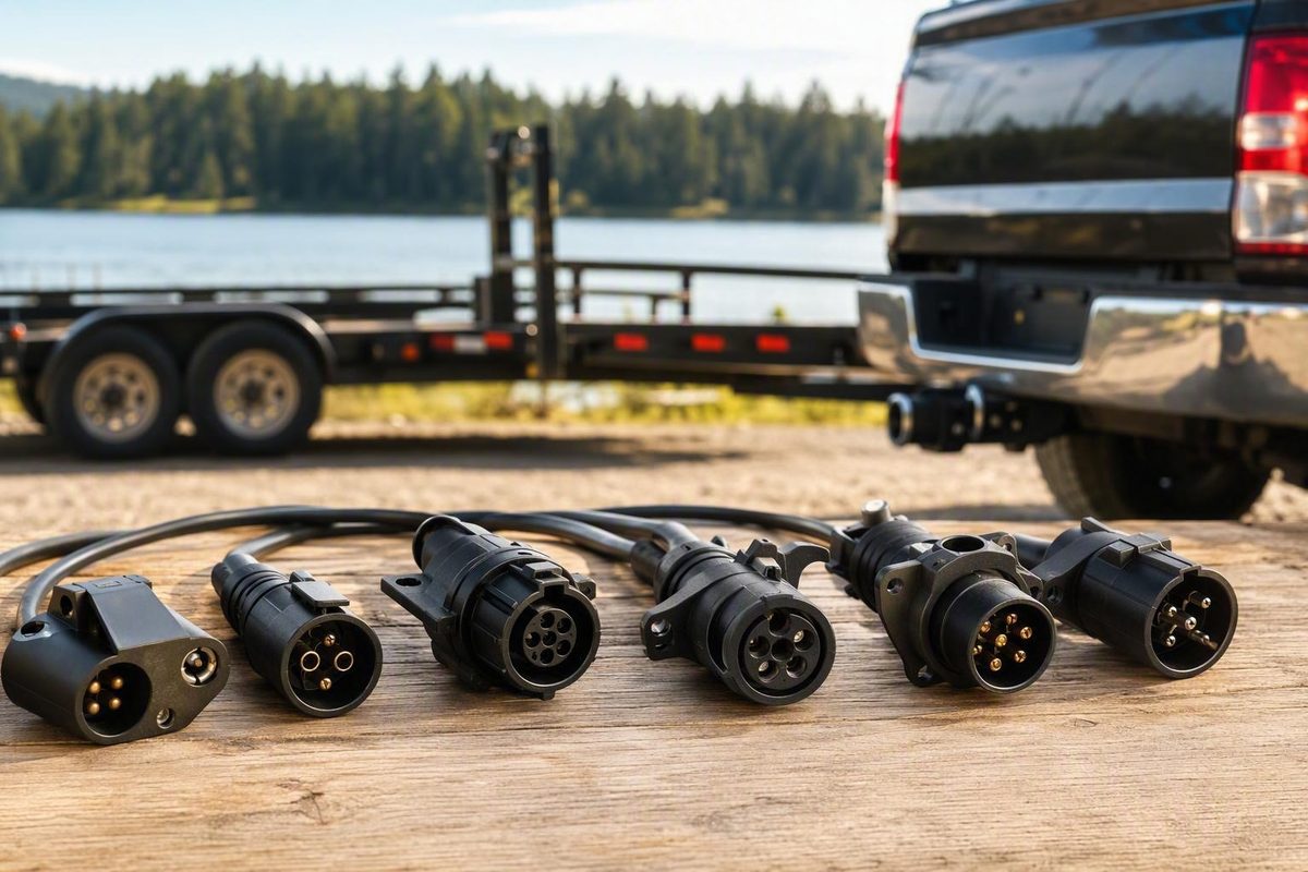
A dependable heavy duty trailer connector is not defined by its pin count, housing weight, price, or product title. Selection starts with compatibility: connector geometry, circuit assignments, operating voltage, brake system, viewing orientation, and whether the component belongs on the tow vehicle or trailer.
Only after those points match should you compare documented current limits, accepted conductor sizes, terminal construction, environmental ratings, strain relief, cable design, serviceability, and mounting. Available catalogs do not provide enough consistent engineering data to rank particular products by durability, so this guide focuses on identifying compatible systems and evaluating the evidence behind product claims.
The connector is also only one part of the installation. Cable, grounding, routing, terminations, mounting, circuit protection, and testing must comply with the instructions for the tow vehicle, trailer, brake controller, connector, and installed equipment.
Start With the Job, Not the Heavy-Duty Label
Before shopping, record:
- Trailer type and intended use
- Tow vehicle or vehicles
- Brake type: none, electric, electric-over-hydraulic, surge, or pneumatic
- Every required electrical function
- Existing vehicle and trailer connectors
- Operating voltage
- Exposure to water, salt, dust, heat, cold, or vibration
- Required cable length and mounting location
- Other tow vehicles or trailers that must remain compatible
“Heavy duty” is used broadly in catalogs and marketplace listings. By itself, it does not establish current capacity, environmental protection, compliance with a named standard, or expected service life. The same caution applies to terms such as waterproof, weatherproof, professional-grade, cold-weather, and corrosion-resistant when no rating, test method, or acceptance criteria are supplied.
Keep connector format separate from connector quality. A seven-contact connector can carry more functions than a four-way connector, but that does not necessarily make it better sealed or more resistant to vibration. Conversely, a well-constructed four-way connector remains unsuitable when the trailer needs electric-brake output, reverse lights, or auxiliary power.
Use this selection sequence:
- Identify the interfaces already installed.
- List every required function.
- Determine the connector family and applicable standard, if any.
- Verify geometry, voltage, circuit assignments, brake compatibility, component side, and diagram orientation.
- Compare documented electrical, environmental, and mechanical specifications.
- Choose the replacement architecture and plan the installation.
- Have every function tested before towing.
Price, stock, customer ratings, purchase counts, and marketplace badges change over time. More importantly, none establishes pinout compatibility, electrical capacity, environmental performance, or service life.
Buyer worksheet
| Field | What to record |
|---|---|
| Trailer type | RV, utility, equipment, boat, gooseneck, fifth-wheel, commercial, agricultural, other |
| Brake system | None, electric, electric-over-hydraulic, surge, pneumatic |
| Tow vehicle | Year, make, model, electrical-system voltage |
| Trailer connector | Shape, contact count, blade or round-pin arrangement, indexing feature |
| Vehicle connector | Shape, contact count, blade or round-pin arrangement, indexing feature |
| Standard | Named standard or connector family, or “unknown” |
| Component side | Vehicle-side socket, trailer-side plug, or another arrangement |
| Required circuits | Ground, tail/marker, stop, turn, reverse, brake output, auxiliary power, ABS power |
| Conductor sizes | Existing size for each circuit and accepted range of proposed terminals |
| Cable length | Connector-to-junction-box or connector-to-harness length |
| Mounting | Bracket, flush mount, nose box, tongue-mounted box, or lead |
| Environment | Water, salt, dust, cold, heat, vibration, frequent coupling |
| Documented ratings | Current, voltage, ingress, temperature, vibration, corrosion, mating cycles |
| Interoperability | Other vehicles or trailers that must remain compatible |
If the connector family, component side, pinout, voltage, or brake arrangement remains unknown after inspection, resolve that uncertainty before comparing products.
Identify the Connector Family Before Comparing Products
“Seven pin” is not a complete specification. It can describe physically and electrically different systems. Count the contacts, but also identify their shape, arrangement, keying, housing, and intended application.
| Connector family | Contacts and shape | Typical housing | Common application | Typical capability to verify |
|---|---|---|---|---|
| 4-way flat | Four inline contacts | Flat molded body | Small utility, boat, and basic-lighting trailers | Ground, tail/marker, combined left stop-turn, combined right stop-turn |
| 4-way round | Four round contacts | Circular body | Some industrial or specialized installations | Usually basic lighting; exact pinout must be checked |
| 6-way round | Six round contacts | Circular keyed housing | Medium trailers, campers, specialized equipment | Basic lighting plus functions such as brakes or auxiliary power |
| 7-way RV blade | Six flat blades around a center contact | Round keyed housing with lid and latch | RVs, equipment trailers, goosenecks, fifth-wheels, larger utility trailers | Basic lighting plus electric brakes, reverse, and auxiliary power |
| SAE J560-type commercial | Seven round pins or mating contacts | Robust circular plug and socket | North American heavy trucks and commercial trailers | Separate lighting functions and ABS or auxiliary power |
| Other seven-contact systems | Varies | Varies | Imported, agricultural, proprietary, or converted equipment | Must be established from documentation |
A four-way arrangement generally supports ground, running or tail lamps, and combined left and right stop-turn functions. Compatible six- and seven-way systems become relevant when additional circuits are needed, such as electric-brake output, reverse lights, or auxiliary power. Lippert’s connector overview describes these general distinctions while also showing that connector formats and color conventions vary (Lippert trailer wiring guide).
RV-style seven-way blade connectors are common in larger consumer towing applications. CURT identifies gooseneck, fifth-wheel, larger utility, and larger boat trailers as typical applications and says a consumer seven-way connection can carry taillight, turn-signal, brake-light, electric-brake, reverse-light, auxiliary-power, and ground circuits (CURT seven-way connector category).
That interface should not be confused with the commercial round-pin system associated with SAE J560. A secondary North American connector overview describes SAE J560 as a heavy-vehicle arrangement used with trucks and trailers equipped with pneumatic brakes. It reports that the connector carries lighting functions and ABS or auxiliary power but does not electrically actuate the pneumatic brakes; air pressure performs the braking action. Because this is standards-specific information drawn from a secondary source, confirm the applicable standard revision and equipment requirements through the vehicle, trailer, and connector documentation before specifying or modifying a commercial system (North American trailer connector overview).
“Utility seven-way” and “RV seven-way” sometimes refer to blade interfaces with matching functions but different wire-color conventions. An etrailer technical reply treats those blade-style pinouts as functionally equivalent while distinguishing commercial round-pin equipment as a separate case that may require conversion (etrailer comparison of RV and utility connectors).
Close-up identification procedure
Before disconnecting anything:
- Count the contacts.
- Distinguish flat blades from small round contacts and commercial round pins.
- Note the arrangement around any center contact.
- Locate the key, notch, lid, latch, or indexing feature.
- Record whether you are looking at the mating face or wiring side.
- Identify whether the component is the vehicle-side socket or trailer-side plug.
- Look for a manufacturer, series, standard, or part number.
- Compare the part with a manufacturer drawing rather than a similarly named marketplace photo.
Do not order from a distant photograph showing only “seven contacts.” Physical mating and electrical arrangement must both agree.
Match Every Required Circuit and Verify the Pinout
Start with functions, not colors. Consumer light-trailer systems commonly combine brake and turn functions on each side. The SAE J560 arrangement described in the supplied secondary reference instead provides distinct left-turn, right-turn, and stop-lamp functions. Do not force both systems into a single “left stop-turn/right stop-turn” model.
| Function | Basic 4-way | Consumer 6- or 7-way | SAE J560-type application | What to verify |
|---|---|---|---|---|
| Ground return | Yes | Yes | Yes | Intended return path and conductor suitability |
| Tail and marker lamps | Yes | Yes | Yes | All intended tail and marker loads |
| Left combined stop-turn | Common | Common | No; left turn is distinct | Source and trailer signal logic |
| Right combined stop-turn | Common | Common | No; right turn is distinct | Source and trailer signal logic |
| Separate stop-lamp circuit | No | Not typical in the described blade arrangement | Yes | Converter requirements |
| Reverse lights or lockout | No | Available on compatible systems | Not assumed | Presence and intended use of reverse signal |
| Electric-brake output | No | Available on compatible systems | Not pneumatic-brake actuation | Compatible controller and trailer brake system |
| Auxiliary or charging power | No | Available on compatible systems | May be assigned as auxiliary or ABS-related power | Switching, protection, voltage, and intended load |
| ABS-related power | No | Not implied by an RV-blade label | Associated with commercial arrangements | Vehicle, trailer, ABS, and standard documentation |
The table is an identification aid, not a universal pinout. Exact assignments require a diagram for the named connector family or standard.
Two seven-contact connectors can disagree because of:
- Blade versus round-pin geometry
- Different keys or indexing
- Combined versus separate stop and turn signals
- Different standards
- Different operating voltages
- Different contact assignments
- Vehicle-side versus trailer-side orientation
- Mating-face versus wiring-side views
- Previous repairs or nonstandard modifications
Use only an identified diagram
A usable diagram should state:
- Connector family or named standard
- Standard revision where relevant
- Vehicle-side socket or trailer-side plug
- Mating-face or wiring-side view
- Indexing position
- Function assigned to every contact
- Intended voltage where relevant
An unlabeled “universal seven-pin diagram” is not enough.
Wire colors are not a substitute for this information. Connector families, replacement leads, manufacturers, and previous repairs may use different conventions. Treat color only as a label after the function has been established.
Bounded verification process
Electrical verification should follow the tow vehicle, trailer, brake-controller, ABS, and connector manufacturers’ procedures. If those procedures are unavailable, or if the system’s standard and voltage cannot be established, use a qualified technician rather than improvising a test.
A competent verification process should establish:
- The intended ground or return conductor.
- The connector family and component side.
- Diagram orientation.
- One circuit function at a time.
- The relationship between source signals and trailer loads.
- The final function assigned to each labeled conductor.
A suitable meter or trailer tester can be used where the applicable instructions authorize it. Sensitive loads should be handled only as directed by their manufacturers. Stop if brake behavior, ABS requirements, circuit protection, operating voltage, or a safe test method remains uncertain.
Define Heavy Duty With Specifications You Can Check
Replace the marketing label with a specification scorecard.
| Specification | What documentation should state | How to evaluate it |
|---|---|---|
| Per-circuit current rating | Limit for each contact and relevant operating conditions | Compare with the documented circuit load; do not infer capacity from pin count |
| Accepted conductor range | Conductor size and, where relevant, insulation diameter | Confirm compatibility with both terminals and seals |
| Terminal construction | Base material, plating, contact type, service parts | Use for compatibility and maintenance planning, not as automatic proof of life |
| Housing material | Material and stated environmental limits | Treat shell strength as one part of the assembly |
| Ingress rating | Named rating, test method, and mated or unmated condition | Check whether the tested condition matches actual installation |
| Corrosion testing | Method, exposure duration, severity, and acceptance criteria | A test name without conditions does not show relevance |
| Vibration testing | Standard, severity, mounting method, and result | Compare the test setup with the connector’s intended mounting |
| Temperature range | Minimum and maximum operating temperatures | Check the connector, cable, seals, and terminals—not just the shell |
| Mating cycles | Number and test conditions | Consider frequency of coupling and maintenance |
| Cable retention | Pullout or retention specification | Check cable diameter and assembly method |
| Strain relief | Supported cable range and retention design | Confirm that it fits the selected cable |
| Applicable standard | Exact standard, revision, and declared scope | A “seven-pin” or “commercial” label does not prove compliance |
| Service parts | Contacts, seals, lids, boots, brackets, and tools | Determine whether damaged parts can be inspected or replaced |
The presence of a test notation is not enough by itself. Ask whether the test covered the complete assembly, whether the connector was mated, how it was mounted, how long the exposure lasted, and what constituted a passing result.
Catalogs show many plausible construction features: die-cast housings, enclosed or concealed terminals, solid or split pins, springs, locking tabs, molded leads, and cold-weather variants. The supplied evidence does not establish through controlled comparison that any one feature produces longer service life.
For example, Grote lists heavy-duty four-way parts 82-1040 and 82-1020 and seven-pole bullet-termination sockets 82-1045 and 82-1046. The catalog identifies 82-1045 with split pins and 82-1046 with solid pins, but it does not provide comparative durability evidence for the two contact styles (Grote trailer connector catalog).
CURT’s catalog similarly illustrates several purchasing formats, including die-cast RV-blade plugs and sockets, a packaged plug-and-socket set, prewired replacement leads, a listed cold-weather assembly, and a dual seven- and four-way vehicle socket. These are examples of available architectures, not a performance ranking.
Pass, verify, or reject
Pass a candidate to the next stage when:
- Connector family and component side match.
- Every required circuit is supported.
- Pin assignments and orientation are documented.
- Voltage and electrical limits are suitable.
- Accepted conductor range matches the installation.
- Necessary environmental and mechanical ratings are documented.
- Test conditions are relevant to the actual mounting and exposure.
Verify before buying when:
- “Waterproof” appears without an ingress rating and test conditions.
- “Corrosion-resistant” appears without material or test details.
- “Cold-weather” appears without an operating-temperature range.
- “Heavy duty” appears without electrical or mechanical data.
- A standards claim lacks a data sheet or declaration.
- The listing does not show the termination and cable-retention method.
Reject the candidate for that application when essential information is missing, including:
- Plug versus socket
- Vehicle side versus trailer side
- Blade versus round-pin geometry
- Pinout and viewing orientation
- Electrical limits
- Accepted conductor range
- Applicable standard
- Voltage compatibility
Choose the Right Replacement Architecture
The same connector family may be sold in several formats. Choose according to the interface being replaced, the available documentation, and the desired maintenance approach.
Six common formats
-
Replacement plug head Reuses the existing trailer cable. It provides access to individual terminations, but correct preparation, assembly, sealing, and cable retention depend on the installer and component instructions.
-
Vehicle-side socket Replaces the fixed receptacle. Check physical depth, mounting pattern, lid clearance, rear-wire protection, and compatibility with the trailer plug.
-
Complete plug-and-socket kit It does not resolve incompatible vehicle signals, voltage, or trailer functions.
-
Molded or prewired lead Moves plug terminations into a factory-assembled section and provides conductors for connection farther back. Its internal construction, conductor specifications, temperature range, and environmental performance still require documentation.
-
Inline extension Adds reach without replacing the original harness. It also introduces additional mating interfaces and cable that must be supported, inspected, and protected.
-
Lead with an accessible junction box Creates a transition between a replaceable connector lead and the permanent trailer harness. It may make circuit identification and access easier, but the box and entries must still suit the location.
A junction box is not proof of environmental protection. Inspect its documented rating, cover arrangement, cable entries, mounting orientation, terminal spacing, conductor retention, and strain-relief provisions.
| Architecture | Terminations exposed to field assembly | Field service access | Installation complexity | Typical replaced section | Adapter dependence |
|---|---|---|---|---|---|
| Serviceable plug head | Plug terminals | High | Medium | Plug only | None when format matches |
| Vehicle-side socket | Rear socket wiring | Medium | Medium | Socket only | None when format matches |
| Plug-and-socket kit | Both sides | High | High | Both interfaces | Usually low |
| Molded or prewired lead | Splice or junction end | Lower at plug | Medium | Complete lead | None when format matches |
| Inline extension | Mating interfaces | High | Low | Extension | May increase |
| Lead with junction box | Box terminals and entries | High | Medium to high | Short lead | None when format matches |
Forum participants discussing repeated RV-blade problems have reported loose terminals, corrosion, vibration-related shorts, and intermittent disconnection. Suggested responses include serviceable components, molded leads, and tongue-mounted junction boxes. These are anecdotal experiences, not controlled evidence that one architecture lasts longer (Airstream owner discussion).
A dual-output seven- and four-way vehicle socket may be convenient when one vehicle tows both basic-lighting trailers and trailers requiring additional circuits. Verify the wiring behind each output: the presence of a seven-way opening does not establish that brake output, reverse, or auxiliary power is connected.
Understand What Adapters Can—and Cannot—Do
An adapter may perform one of three different jobs:
- Passive physical adaptation: Repositions existing circuits between connector shapes.
- Signal conversion: Changes electrical logic, such as separate stop and turn signals into combined stop-turn functions.
- Voltage conversion: Changes or conditions voltage for a different electrical system.
Do not assume that a product called an “adapter” contains conversion electronics.
It cannot generate:
- Brake-controller output
- Reverse-light input
- Protected charging or auxiliary power
- ABS power
- A missing ground
- Compatible stop-turn logic
- Compatible operating voltage
The 4-way-to-7-way example
The remaining contacts do not become functional merely because the destination has more positions. Electric brakes require an appropriate brake-control source; reverse and auxiliary functions require their corresponding source circuits.
Manufacturers offer adapters among four-way flat, four-way round, six-way round, seven-way round, and seven-way blade formats. That catalog variety demonstrates physical-conversion options, not the presence of every destination function (Husky connector and adapter catalog).
| Source format | Destination format | What may pass through | What remains unavailable if absent at source | What else may be required |
|---|---|---|---|---|
| 4-way flat | 7-way RV blade | Four basic lighting functions | Brake output, reverse, auxiliary power | Additional source circuits and controls |
| 7-way RV blade | 4-way flat | Ground and basic lighting | Brakes, reverse, auxiliary power at four-way output | No added functions at four-way |
| 6-way round | 7-way blade | Correctly mapped existing circuits | Any unwired source function | Pin mapping and possible rewiring |
| RV/utility blade | Commercial round pin | Only compatible, correctly converted signals | Differently arranged or unsupported functions | Signal conversion may be required |
| SAE J560-type | ISO 1185-type | Not established by physical similarity | Differently assigned or incompatible functions | Standard-specific and possible voltage conversion |
| Specialized system | Common RV blade | Depends on original system | Unsupported functions | Documented custom conversion |
Adapting between RV or utility blade formats is not the same as converting to or from a commercial round-pin arrangement. Commercial systems may separate stop and turn functions, so a neat pin-to-pin cable can still be electrically wrong.
The supplied secondary standards overview reports that SAE J560 and ISO 1185 can be physically similar while differing electrically and may require voltage conversion for interoperability. Treat shell fit as identification evidence only, and verify the applicable standards, voltage, assignments, and auxiliary or ABS function from authoritative equipment documentation.
Changing both sides to an uncommon connector creates an operational trade-off. The primary interface may suit the intended application, but rental equipment, service vehicles, or other trailers may then require adapters. Those additional interfaces must also be identified, inspected, and tested.
For every adapter, verify:
- Vehicle side and trailer side
- Plug, socket, male, and female terminology
- Source and destination formats
- Pinout at both ends
- Viewing orientation
- Passive or electronic construction
- Supported voltage
- Supported functions
- Per-circuit limits
- Treatment of unused contacts
Build Durability Into the Whole Connection System
Connector performance depends partly on the surrounding installation. Evaluation should include:
- Plug and socket
- Contacts and seals
- Cable and conductors
- Return path
- Terminations
- Mounting
- Routing and abrasion protection
- Cable retention and strain relief
- Circuit protection
- Junction points
- Access for inspection and testing
Trailer owners have reported moisture intrusion, corrosion, vibration, loose terminals, poor grounds, exposed routing, cold-stiff cable, and cable movement as failure modes. These reports are anecdotal and should be treated as inspection prompts rather than proof that a particular product or cable type is universally better (Grassroots Motorsports trailer-wiring discussion).
Match conductor and terminal to the circuit
Do not prescribe one wire size for every trailer. Determine conductor suitability from the applicable vehicle, trailer, controller, and component documentation, considering:
- Documented load
- Circuit length
- Permitted voltage drop
- Operating voltage
- Insulation and environmental requirements
- Bundling and routing
- Terminal conductor range
- Connector per-circuit limit
Evaluate the documented return-path design rather than assuming that connector contact count or frame attachment alone guarantees a suitable ground. Any frame bonds or dedicated return conductors should follow the equipment documentation and remain accessible for inspection.
Plan the physical layout
When comparing proposed layouts, look for documented provisions for:
- Secure socket mounting
- Complete plug seating and latch engagement
- Cable length sufficient for articulation without road contact
- Strain relief compatible with the cable
- Routing away from identified heat, abrasion, pinch, and movement hazards
- Protected and accessible junction points
- Compatible branch-connection systems
- Durable function labels
- Inspection and test access
Sealed crimps and adhesive-lined heat-shrink components are commonly discussed for exposed low-voltage wiring, but the supplied evidence does not establish one universal termination method. Use only terminals, seals, tooling, and procedures approved for the selected wiring system.
Similarly, forum recommendations for marine wire, direct-burial cable, extension cord, SO cable, or SOOW cable do not establish approval for every trailer. Cable selection must come from the requirements applicable to the vehicle, trailer, routing, equipment, and jurisdiction.
Follow the tow vehicle, trailer, brake-controller, and component instructions for circuit protection. Do not select a fuse or breaker from connector pin count or an unsourced internet diagram.
For readers working on compatible sealed low-voltage branch connectors, Plug It Right publishes a Deutsch DT kit and crimping guide. That article is contextual instruction, not evidence that a Deutsch DT connector is automatically suitable for a main trailer interface. Circuit count, contact capacity, wire range, mating design, tooling, and environmental documentation must independently match the branch application.
Test Before Towing and Troubleshoot by Function
Testing should be organized by confirmed function rather than wire color and performed according to the vehicle, trailer, controller, ABS, and connector instructions. This section is a diagnostic framework, not a substitute for those procedures.
Post-installation sequence
-
Ground integrity Confirm the intended return path through the specified connector contact.
-
Tail and marker lamps Operate the running-light circuit and verify the intended trailer lamps.
-
Left-side turn and stop behavior Verify whether the system uses a combined stop-turn function or separate functions.
-
Right-side turn and stop behavior Repeat independently for the right side.
-
Reverse function Where installed, verify the documented reverse-lamp, lockout, or other assigned function.
-
Electric-brake output Where fitted, follow the brake-controller and trailer-brake test instructions. Do not improvise a test for an unfamiliar brake system.
-
Auxiliary or charging power Confirm when the circuit is intended to be live and what documented load it supplies.
-
ABS-related power On applicable commercial equipment, follow the vehicle, trailer, ABS, and connector documentation rather than treating the contact as a general accessory source.
Any loaded or dynamic test should be performed only where authorized by the equipment procedures and by someone with the appropriate equipment and competence.
Divide the system into sections
A suitable tester or meter can help a competent technician isolate:
- Tow-vehicle wiring
- Vehicle-side socket
- Plug and lead
- Junction or transition point
- Trailer harness
- Branch connection
- End load
An accessible junction point may provide a convenient boundary between a replaceable plug lead and the permanent harness.
Troubleshooting an intermittent fault
With the system de-energized or otherwise placed in the condition required by the manufacturer’s procedure, inspect:
- Connector seating
- Latch and lid engagement
- Loose or backed-out terminals
- Bent, spread, worn, or contaminated contacts
- Corrosion or discoloration
- Evidence of water entry
- Movement at the cable entry
- Split, damaged, or hardened cable jacket
- Unsupported cable
- Loose mounting hardware
- Return conductors and documented bonding points
- Junction-box covers and entries
- Chafing at frame openings or moving assemblies
Do not manipulate unfamiliar energized brake, ABS, or power circuits as a generic troubleshooting technique. For suspected miswiring, isolate the affected equipment as directed and map one circuit at a time rather than moving conductors according to color assumptions.
If connector heads repeatedly fail, investigate the complete installation before fitting another identical part. Relevant inspection points include cable retention, mounting movement, terminal method, water entry, routing, and conductor-to-terminal compatibility.
Obtain professional diagnosis before towing when the system has unexplained brake operation, overheating, melted insulation, recurring circuit-protection operation, uncertain standards, ABS faults, or incompatible voltages.
Use a Final Compatibility and Buying Checklist
Use this decision tree before ordering:
- Identify the trailer and brake system.
- Inventory every required electrical function.
- Identify both existing connector interfaces.
- Confirm connector family, applicable standard, and voltage.
- Compare functions using diagrams with stated side and orientation.
- Decide whether to retain the format, adapt it, or replace both sides.
- Select a plug head, socket, matched kit, molded lead, extension, or junction-box lead.
- Verify documented electrical, conductor, mechanical, and environmental limits.
- Plan mounting, routing, return path, strain relief, and circuit protection from the applicable instructions.
- Arrange function-by-function testing before towing.
Nonnegotiable ordering details
Confirm:
- Vehicle-side or trailer-side component
- Plug or socket
- Blade or round-pin contacts
- Contact count and physical arrangement
- Keying and indexing
- Applicable standard and revision where relevant
- Mating-face and wiring-side diagram orientation
- Operating voltage
- Required functions
- Accepted conductor range
- Per-circuit ratings
- Cable length and specification
- Mounting pattern and clearance
- Included bracket, cover, boot, hardware, seals, or contacts
- Required terminal tools
- Availability of replacement contacts, seals, lids, and brackets
For wet, salty, cold, dusty, or high-vibration service, request:
- Ingress rating, test method, and mated or unmated condition
- Operating-temperature range
- Terminal material and plating
- Corrosion-test method, duration, severity, and acceptance criteria
- Vibration-test method, severity, mounting, and result
- Cable-retention data
- Strain-relief cable range
- Mating-cycle rating
- Inspection and maintenance instructions
Confirm not only that the connector has enough contacts, but that the tow vehicle provides every required controller, signal, return, and protected power source. An empty contact position is not a powered circuit.
Interoperability belongs in the selection decision. A specialized connector that requires adapters for routine equipment may create more interfaces to identify and maintain. A common format, however, should not be retained when it cannot meet the documented electrical or environmental requirements.
Keep the following with the trailer’s maintenance records:
- Manufacturer and part number
- Connector family and standard
- Vehicle-side and trailer-side diagrams
- Diagram orientation
- Verified function at each contact
- Conductor labels and sizes
- Circuit-protection information
- Test results
- Installation date
- Replacement contact and seal details
There is no universal winner. The appropriate heavy duty trailer connector is the documented interface whose geometry, standard, voltage, circuit functions, conductor limits, and component side match the tow vehicle and trailer. The surrounding installation must also follow the relevant equipment requirements for mounting, routing, cable retention, grounding, circuit protection, and testing.
Is every 7-pin trailer connector compatible with every 7-way socket?
No. Seven contacts do not guarantee compatible geometry or electrical assignments. RV blades, commercial round-pin connectors, and other seven-contact systems can differ in contact shape, keying, voltage, signal logic, pinout, brake application, and orientation.
Even when two connectors physically mate, verify the functions, component side, and diagram view. RV and utility blade terminology may sometimes describe matching functions with different wire colors, but that does not establish compatibility with commercial round-pin equipment.
What is the difference between an SAE J560 connector and a 7-way RV blade connector?
SAE J560 is associated with North American heavy trucks and commercial trailers, including pneumatic-brake applications. The commercial round-pin electrical interface carries lighting functions and ABS or auxiliary power; it does not electrically actuate the pneumatic brakes.
A seven-way RV blade connector uses flat blades and is common on larger consumer towing applications. It can support combined stop-turn lighting, electric-brake output, reverse, auxiliary power, and ground when those functions are installed. The two systems are not interchangeable merely because both have seven contacts.
Can a 4-way-to-7-way adapter add trailer brakes and auxiliary power?
No. A passive adapter can route the four existing basic-lighting functions into a seven-way housing, but it cannot create brake-controller output, reverse input, or auxiliary power.
Some adapters provide separate leads for additional circuits. Those leads still require valid, correctly controlled, and appropriately protected source circuits installed according to the applicable equipment instructions.
Is a molded 7-way cable better than a replaceable plug head?
Not universally. Its conductor specifications, internal construction, temperature range, sealing, and strain relief still require documentation.
A replaceable head provides direct access to individual terminals, but its result depends on compatible conductors, terminals, seals, tooling, cable retention, and correct assembly. Choose according to the documented environment, maintenance plan, and installer capability.
Can I identify trailer connector circuits by wire color?
Do not rely on color alone. Colors can vary among connector families, manufacturers, replacement leads, wiring conventions, and previous repairs.
Identify the connector from its documentation, confirm the component side and diagram orientation, and verify each circuit by function using an authorized procedure. Label the conductors only after their functions have been established.