
6 min read ·
Trailer Wiring Junction Box: Match Functions, Not Colors
Choose a trailer wiring junction box by terminal fit, circuit load and sealing, then connect verified functions and test lights, brakes and grounds.
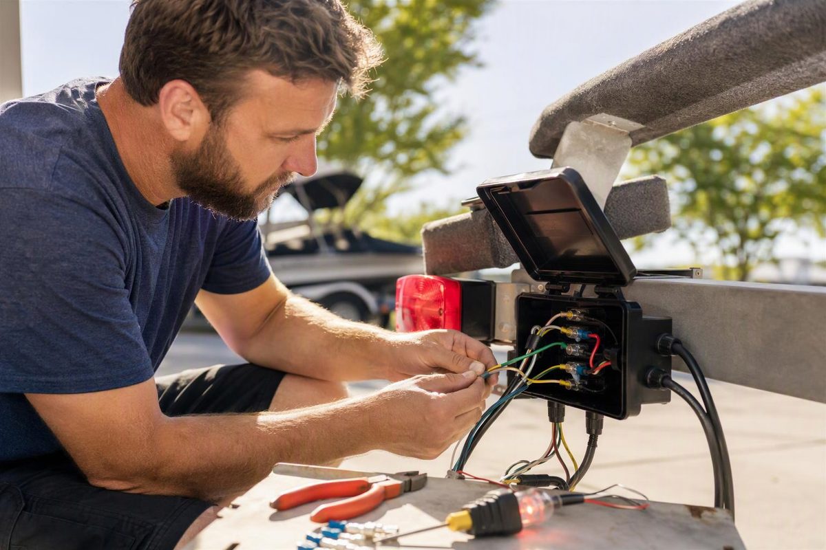
A trailer wiring junction box provides an accessible connection point between the trailer’s plug cable and its wiring to lights, brakes and other equipment. For a common 7-way RV-blade setup, choose a box with seven electrically isolated terminals, suitable current ratings, cable-entry seals and enough room for the required ring terminals.
The essential wiring rule is function to function—not color to color. A colored stud is an organizer, not proof that a same-colored wire belongs there. CURT documents different color assignments for traditional and SAE RV-blade cables, and etrailer’s junction-box installation demonstrates testing each circuit before connecting it. CURT wiring guide; etrailer installation transcript
What to check before buying
A plain stud-type junction box joins conductors; it does not convert lighting signals, operate the brakes or provide overcurrent protection unless those components are specifically included.
Check these details:
- Isolated terminals: Each different circuit needs its own connection point. Do not substitute a common busbar that connects all studs together. With all wiring removed from the box, a continuity check between studs can confirm whether terminals are isolated.
- Electrical ratings: Match voltage and each terminal’s current capacity to the circuit. Account for the combined return current through a shared ground terminal. Seven studs alone tell you nothing about amperage capacity. Do not route winch-motor power through an unrated trailer-lighting box.
- Terminal fit: Match each ring terminal to both the conductor’s AWG size and the stud diameter. Check clearance between neighboring rings and under the lid.
- Cable entries: Grommets or glands must fit the actual cable outside diameter. Check for clamps that hold the cable jacket and plugs for unused entries.
- Environmental protection and access: Look for documented sealing appropriate to the mounting location. “Weather-resistant” is not evidence of an immersion rating. Leave space to remove the lid and use tools on the terminals.
As examples of construction—not a universal specification—Buyers Products lists its 5601100 as a seven-terminal polypropylene box and its 5601101 as a seven-terminal ABS box with color-coded terminals. Confirm the exact model’s electrical ratings, seals and included hardware separately. Buyers Products specifications
Ring-terminal sizes are separate choices: Ancor’s catalog lists multiple screw-hole sizes within each wire-gauge range, including 16–14 AWG and 12–10 AWG. Choose a terminal that fits both ends of the connection. Adhesive-lined heat-shrink versions can seal the wire-entry end when properly installed; they do not seal the exposed stud connection. Ancor terminal catalog
Map the circuits before moving wires
The table below is a function checklist, not a terminal-position diagram. It applies to a typical 7-way RV-blade trailer with combined stop/turn lamps. Record the actual cable color and box terminal beside each verified function.
| Circuit | What connects at that junction |
|---|---|
| Ground/return | Plug ground, trailer circuit returns and specified chassis bond |
| Tail/running lights | Feed to tail, marker, clearance and other applicable running lamps |
| Left stop/turn | Left combined brake-light and turn-signal feed |
| Right stop/turn | Right combined brake-light and turn-signal feed |
| Electric-brake output | Brake-controller output to the trailer brake circuit |
| +12 V auxiliary | Supply to the approved charging or accessory circuit |
| Reverse | Reverse lamps or the specified reverse-operated equipment |
These functions are shown in CURT’s RV-blade wiring diagrams. Leave unused circuits unconnected and safely insulated.
Before identifying plug contacts, establish the connector family and whether your diagram shows the front mating face or rear wire-entry side. The junction box’s left-to-right stud order is not the plug’s pin order. Use the 7-pin wiring diagram identification guide if the connector or viewing direction is uncertain.
With power isolated and the cable conductors disconnected from other circuits, use continuity to map each plug contact to its cable conductor. Identify outgoing wires from the trailer’s diagram, physical tracing or function testing. For lamp circuits, etrailer demonstrates using a trailer test box or tow vehicle to activate one function at a time; isolate power again before changing connections. Follow the equipment instructions for brake and charging circuits rather than applying power to unidentified wires. Function-testing demonstration
Install without loading the terminals mechanically
- Document and isolate. Photograph the existing wiring and label verified functions. Unplug the tow vehicle and isolate trailer batteries and other power sources before cutting, crimping or checking continuity.
- Choose a protected location. Keep the box clear of moving parts, road-debris strikes and likely submersion. Allow the plug cable enough movement for turns without dragging or pulling on the box. Check behind any proposed drilling point.
- Route through seals first. Pass cables through the correct entry fittings before attaching ring terminals. Clamp the outer jacket where the box provides a cable clamp; the stud connections should not carry cable tension.
- Prepare sound conductors. Cut back damaged or corroded wire to clean copper. Strip to the terminal maker’s specified length, use the matching crimp tool and inspect each crimp. Follow the terminal instructions for heat shrinking.
- Join matching functions. Place the incoming and outgoing conductors for one circuit on its assigned stud. Do not overcrowd the stud or put different functions together. Follow the box maker’s hardware arrangement and torque specification.
- Close and label. Keep rings and exposed copper clear of adjacent terminals. Seat entry seals and unused-entry plugs, then close the lid without pinching wires. Retain a circuit map for later repairs.
Etrailer’s Buyers-box demonstration shows entry fittings, jacket clamps and ring-terminal connections; it also notes that ring terminals and mounting screws are not included with that particular kit. Installation transcript
Do not select brake wiring by what fits inside the box. For example, Dexter specifies a recommended minimum 10 AWG copper hookup wire for four brakes at a 30–50 ft hitch-to-axle distance. Follow the applicable brake-system instructions for wire sizing, including the return path. Dexter service manual, trailer wire-size chart
Keep brake-controller output separate from permanent +12 V auxiliary power. Where a breakaway system joins the brake circuit, follow that kit’s diagram rather than copying another kit’s colors. CURT’s 52041 instructions, for example, connect the switch output to the brake feed and specify a separate auxiliary charging connection. CURT 52041 installation manual
Test before towing
Reconnect power only after checking for stray strands, loose rings and unintended contact between terminals. Verify running lamps, left and right turn signals, brake lights and reverse equipment where fitted. Test combinations, such as running lamps plus braking, not just each function separately.
For electric brakes, follow the controller manufacturer’s test procedure and verify operation beyond the junction box. A voltage reading at the stud does not prove adequate voltage reaches the brake magnets. Dexter identifies loose or corroded connections as sources of increased resistance and reduced magnet voltage. Dexter electrical troubleshooting guidance
If several lamps dim or interact, check the shared ground/return path. If one circuit fails, compare its input at the box with its outgoing connection and downstream wiring under load. Replace damaged terminals and correct the water-entry cause rather than merely tightening corroded hardware.
For the breakaway test, disconnect the trailer plug from the tow vehicle first and follow the kit’s instructions. CURT warns that testing its breakaway system while connected can severely damage the tow vehicle’s brake controller. Restore the switch pin after testing; the breakaway system is not a parking brake. CURT breakaway safety instructions