
4 min read ·
Match the connector family, diagram view and circuit functions before using any 7-pin wiring diagram.
Identify the 7-pin trailer connector, select the correct pinout, and verify every circuit by function instead of trusting wire color.
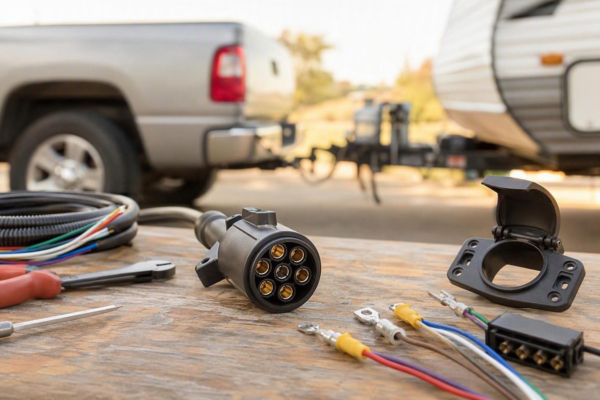
A 7-pin wiring diagram is not universal. First identify the connector family, whether it is the vehicle socket or trailer plug, and whether the drawing shows the mating face or rear cable-entry side. Those two views are mirror images.
For a North American connector with six flat blades around one center contact, start with the 7-way RV blade table below. Do not apply it to a seven-round-pin connector.
North American 7-way RV blade wiring
Two commonly published color schemes assign the same seven functions differently. CURT distinguishes its “traditional” configuration from the SAE J2863 configuration, so match the circuit function and terminal marking, not color alone (CURT wiring guide).
| Circuit function | Traditional color | SAE J2863 color |
|---|---|---|
| Ground return | White | White |
| Electric-brake output | Blue | Blue |
| Tail/running lights | Green | Brown |
| Left turn and stop | Red | Yellow |
| Right turn and stop | Brown | Green |
| +12 V auxiliary supply | Black | Orange |
| Reverse lights | Yellow | Gray |
This table identifies circuits, not visible clock positions. Use labels molded beside the replacement connector’s terminals and check whether its instructions depict the plug or socket.
For the physical blade layout and view-selection procedure, use Which 7-Way Trailer Connector Wiring Diagram Applies?. For wiring electric brakes beyond the plug, see 7-Way Trailer Wiring With Brakes.
Do you have a different seven-contact connector?
| Connector | How it differs |
|---|---|
| North American 7-way RV blade | Six flat blades around one center contact; common on light-duty vehicles, RVs and trailers |
| North American 7-way round | Seven round contacts; its allocation differs from the RV blade |
| SAE J560 primary | Heavy-duty round truck-to-trailer connector with commercial lighting and ABS power circuits |
| ISO 1724 Type N | 12 V lighting connector with a rear-fog circuit, but no reversing-light or steady-positive contact |
| Australian 7-pin flat or round | Uses a regional allocation; shape and cable-entry orientation still need to match the selected diagram |
Seven contacts do not establish compatibility. Seven-Pin Trailer Connectors: Types and Compatibility explains the shape, keying and application differences.
ISO 1724 Type N pinout
ISO 1724 Type N is a 12 V, seven-contact lighting connector. It has neither a reversing-light circuit nor a steady-positive supply; the cited standards summary directs those applications to a supplementary seven-pin or 13-pin system (Erich Jaeger’s ISO 1724 reference).
| Pin | Function | Standard color |
|---|---|---|
| 1 | Left turn | Yellow |
| 2 | Rear fog light | Blue |
| 3 | Common return | White |
| 4 | Right turn | Green |
| 5 | Right rear/marker/position and license-plate lamps | Brown |
| 6 | Brake lights | Red |
| 7 | Left rear/marker/position and license-plate lamps | Black |
SAE J560 primary pinout
Do not use an RV-blade diagram on an SAE J560 connector. J560 is a North American 12 V heavy-duty truck/trailer interface. The standard also defines a separate auxiliary connector; primary and auxiliary versions are not interchangeable because their contact layouts differ (Erich Jaeger’s SAE J560 reference).
| Contact | Function | Color |
|---|---|---|
| 1 | Ground return | White |
| 2 | Clearance, side-marker and identification lamps | Black |
| 3 | Left turn and hazard lamps | Yellow |
| 4 | Stop lamps and secondary ABS power | Red |
| 5 | Right turn and hazard lamps | Green |
| 6 | Tail, license-plate, clearance and/or side-marker lamps | Brown |
| 7 | Continuous primary ABS power/auxiliary devices | Blue |
Verify an unknown connector before towing
- Record the view. Note whether you are looking into the mating face or at the rear wire-entry side.
- Read the housing. Terminal numbers and molded function abbreviations outrank assumed wire colors.
- Disconnect power before continuity tests. On the trailer side, trace each conductor to its destination or documented ground network.
- Test vehicle-socket outputs individually. Check running lights, left turn, right turn, brake output, reverse and auxiliary power only under the conditions that activate each circuit.
- Size and protect powered circuits correctly. The auxiliary supply and brake-controller output must follow the vehicle, controller and trailer requirements.
- Test the assembled trailer. Confirm every lamp and the electric brakes before road use.
If the connector family, component side or viewing direction remains uncertain, stop before moving wires. A correctly colored wire on the wrong terminal is still a wiring fault.