
6 min read ·
Choose the Right Connector for Your Low-Voltage Circuit
Compare low-voltage wire connectors by current, wire fit, sealing and service needs, then avoid common crimp, pinout and weatherproofing errors.
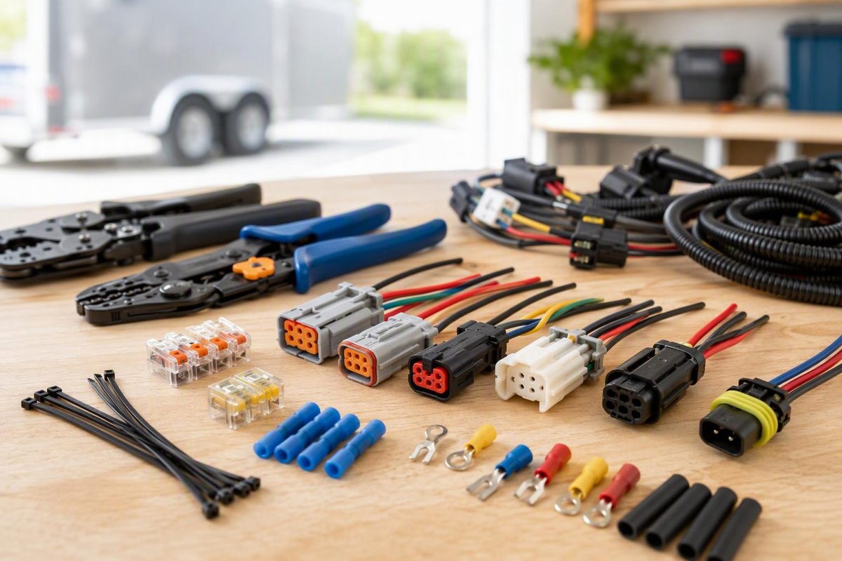
Choose a low-voltage wire connector by circuit function, maximum current, conductor size, insulation diameter, environment and need for disconnection. Voltage alone does not settle the choice. A connector sold for 12 V can still be wrong if its contacts are undersized, its seals do not fit the cable or its pinout does not match the equipment.
Select the connection, environment and wire fit to narrow the connector type.
Connector Fit Check
This identifies a connector style, not a current rating. Confirm the exact contact specifications before installation.
Use a Purpose-Rated Heat-Shrink Butt Splice
This suits a permanent exposed wire-to-wire repair when its conductor range, crimp requirements and shrink temperature match the job.
Check the finished seal and support the loom so movement does not reach the splice.
Source note: Recommendations reflect the cited TE Connectivity, 3M and Anderson manufacturer documentation; exact ratings depend on the selected part, wire and assembly conditions.
Use a removable connector where servicing requires separation and a permanent splice where it does not. A dry-location connector needs additional protection if road spray can reach it. Twist-and-tape joints are not a durable harness repair.
Match the Contact to the Actual Circuit Current
Start with the load’s maximum continuous current and any startup or inrush current. Then check the manufacturer’s rating for the specific contact, wire and housing configuration, not merely the product-family name printed on a listing.
Current ratings are conditional. For example, a Molex specification says allowable current depends on connector size, contact material, plating, ambient temperature, PCB characteristics and related factors. Its table is based on one energized circuit and no more than a 30°C temperature rise (Molex product specification). Closely packed loaded cavities, hot engine compartments and small conductors can therefore require a lower limit than a headline rating suggests.
Also size and fuse the wire for the circuit. A fuse protects the circuit conductors against overcurrent; it does not make an undersized connector acceptable. For conductor sizing, see what determines the required wire gauge.
Match Conductor Size and Insulation Diameter
AWG describes conductor size, but seals and insulation-support wings fit the wire’s outside diameter. Two 16 AWG wires can have different insulation diameters. TE’s crimping guide specifically notes this distinction and requires the terminal’s insulation support and tooling range to accommodate the wire’s outside diameter (TE crimping guide).
This also matters with sealed connectors. TE lists Deutsch DT for 14–20 AWG (2.50–0.50 mm²), size 16 contacts and 13 A per contact. The family uses rear wire seals and an interface seal, and TE conditions its stated performance on using proper parts, procedures and tooling (TE Deutsch DT specifications). Select the exact contact for the conductor and confirm that the cable insulation falls inside the specified seal range for the chosen part.
A terminal that is too large may not compress correctly around the strands. One that is too small can cut strands or fail to accept the conductor. A mismatched cable seal may look assembled while leaving a path for water.
Choose Sealing and Strain Relief for the Installation
For an interior electronics cabinet, an unsealed connector may be sufficient. Under a hood, below a trailer frame or on agricultural equipment, use a connector system documented for the expected water, dirt, vibration, temperature and fluids.
“Sealed connector” describes a complete system, not just a plastic shell. The correct contacts, wire seals, interface seal, secondary lock and cavity plugs all matter. A published ingress rating applies only under the manufacturer’s stated test and assembly conditions; it is not proof that an open, partly assembled or poorly crimped connector will remain dry.
For a permanent exposed splice, a purpose-rated heat-shrink butt connector can combine a crimped conductor joint with environmental protection. As one documented example, 3M specifies a seamless copper barrel, tin plating and transparent heat-shrink insulation designed to resist water, salt and other contaminants after crimping and shrinking (3M Scotchlok heat-shrink butt connectors). Match the product’s wire range and temperature rating to the job rather than buying by sleeve color alone.
Strain relief is separate from sealing. Secure the cable or loom so vibration, pulling and flexing are not carried by the contact or splice. A watertight connector can still fail mechanically if the cable moves at the terminal.
Do Not Assume Every Power Connector Is Weatherproof
Anderson Powerpole is useful for modular DC power connections, but the contact and housing must be identified precisely. Anderson’s PP15–45 literature covers 20–10 AWG (0.75–6 mm²) and capabilities up to 55 A per pole, with the applicable contact and temperature chart determining the rating. It rates the finger-proof housing only IP20, while describing the standard housing as having an open interface. Neither should be treated as a sealed underbody connector without suitable environmental protection (Anderson PP15–45 data sheet).
For exposed multi-circuit harnesses, compare purpose-built sealed families. The Weather Pack selection and crimping guide and Deutsch DT kit guide cover two common options.
Select the Connector Style by Connection Type
A permanent wire-to-wire repair generally calls for a crimp butt splice. Where moisture can reach the joint, use a purpose-rated heat-shrink version and confirm its conductor range, required crimp die, shrink temperature and finished seal.
A removable multi-circuit connection on a vehicle or outdoors calls for a sealed automotive connector system, provided its contacts, seals, current capacity and cavity count suit the circuit. Buy or identify the complete mating pair, including its contacts, locks and any plugs for unused cavities.
A removable two-pole accessory connection can use a purpose-rated power connector such as Anderson Powerpole when its current and wire specifications fit. If the location is wet or dirty, the open connector needs separate environmental protection or replacement with a connector documented for that exposure.
For a cable attached to a battery, bus bar or grounded stud, use a crimp ring terminal matched to the conductor and stud diameter. Also check its metal, plating, insulation and any required protective boot.
For a switch, relay or appliance tab, use a receptacle matching the tab’s width and thickness. Confirm current capacity, locking method and insulation support; use the OEM housing where the application requires one.
Verify the Pinout From a Defined View
Before inserting contacts, draw a cavity map and label it mating face or wire-entry side. Those views are mirror images. Record each cavity by function—power, ground, left turn or sensor return—not just wire color. Color is useful documentation, but it is not proof of function in an unknown or previously repaired harness.
Check housing part numbers, cavity markings, keying and the mating half. Then verify unknown circuits electrically. Trailer connectors are especially easy to misidentify; trailer connector selection starts with functions and connector family.
Crimp, Assemble and Test the Connection
- Disconnect the power source and confirm the circuit is de-energized.
- Strip only the length specified for the terminal without nicking or removing strands.
- Use the terminal manufacturer’s specified crimper or a validated die made for that terminal style and wire range.
- Position the conductor and insulation exactly as the terminal instructions show. On terminals with separate open barrels, strands belong in the conductor barrel and insulation in the support barrel.
- Complete the ratchet cycle, then inspect conductor position, crimp formation and insulation support against the terminal maker’s criteria.
- Insert the contact until it locks; gently pull back to confirm retention. Fit the secondary lock and any required cavity plugs.
- Secure the loom so vibration or movement is not carried by the terminal.
- Test polarity and function, then measure voltage drop with the circuit operating normally.
TE’s guide emphasizes matched wire, terminal and tooling, clean stripping, correct placement and proper insulation support. It shows that over-crimping can crush strands, while under-crimping leaves inadequate support (TE crimping guide). A light pull check can catch a gross assembly error, but it does not replace the terminal maker’s crimp-height or pull-force specification.
If a completed connection shows normal voltage with no load but fails when the accessory runs, follow a loaded voltage-drop testing workflow. That separates connector resistance from power-source, wire and ground faults.