
6 min read ·
Match and Crimp Weather Pack Connectors Correctly
Learn how to match Weather Pack housings, terminals and cable seals, apply the 20 A ceiling, map cavities and make a reliable open-barrel crimp.
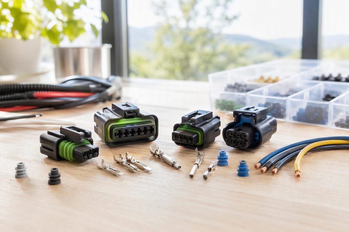
Weather Pack connectors suit low-voltage circuits exposed to moisture, dirt, chemicals and temperature changes, but only when the housings, terminals, cable seals and cavity plugs match. Select by complete housing part number, cavity layout, conductor size, insulation diameter, circuit current and environment—not by appearance or wire color.
A legacy Delphi system sheet lists a 20 A continuous maximum, a 0.35–3.0 mm² cable range and a -40°C to 125°C temperature range. These are system limits, not a promise that every cavity can carry 20 A in every harness. The published current curves are based on one circuit in free space and do not account for every variable, including adjacent loaded circuits and bundling (Weather Pack system data). Check the specifications for the exact components and installation.
Enter the measured insulation diameter and planned current to find the listed seal range and flag the 20 A ceiling.
Selection Result
Green seal
2.50 mm is within the published 2.03–2.80 mm range. 10 A is below the published 20 A system ceiling; verify the actual terminal, temperature, bundling and loaded-cavity conditions.
Published Seal Ranges
- Red
1.29–1.70 mm - Green
2.03–2.80 mm - Gray
2.81–3.49 mm - Blue
3.45–4.30 mm
Source: Weather Pack component table; 20 A ceiling from legacy Delphi system data.
Eight Details Must Match Before Assembly
| Item | Selection Check |
|---|---|
| Housing pair | Confirm the complete part number of each mating half. Equal cavity counts do not prove compatibility. |
| Circuit layout | Common bodies have 1, 2, 3, 4-inline, 4-square or 6 cavities. The two four-way layouts differ. |
| Terminals | Use the specified pin and sleeve contacts for the housing and conductor size. |
| Cable seal | Match the seal to the outside diameter over the insulation, not AWG alone. |
| Empty cavities | Install the specified cavity plug in every unused position. |
| Crimp tool | Use a die intended for Weather Pack open-barrel terminals and the applicable wire range. |
| Electrical load | Check normal and startup current, ambient temperature, duty cycle, bundling and voltage drop. |
| Pinout | Record the cavity number, viewing side and connector half; verify function instead of trusting color. |
In a conventional inline connection, the shroud housing carries male pin terminals and the tower housing carries female sleeve terminals. Housing descriptions such as “male” and “female” can therefore be ambiguous. Match part numbers rather than seller shorthand.
For example, Aptiv drawing 12015792 specifies female terminal 12089188 for the inline tower assembly and mating shroud housing 12010973 (Aptiv drawing 12015792). That example establishes the specified pairing for those components, not every housing in the family.
Match the Seal to the Insulation Diameter
Insulation thickness varies among automotive wire constructions. Two wires with the same conductor gauge can therefore require different seals. Measure the finished wire over its insulation rather than choosing from AWG alone.
One published Weather Pack component table gives these ranges:
| Seal Color | Insulated-Wire Diameter |
|---|---|
| Red | 1.29–1.70 mm |
| Green | 2.03–2.80 mm |
| Gray | 2.81–3.49 mm |
| Blue | 3.45–4.30 mm |
The gray and blue ranges overlap from 3.45 to 3.49 mm. A measurement in that interval matches both published ranges, so follow the specification for the selected housing, terminal and seal rather than choosing by color alone.
The same component table lists common loose-piece terminal sizes of 20–18 AWG, 16–14 AWG and 12 AWG (Weather Pack component table). The terminal must match the conductor, while the seal must match the outside diameter over the insulation. Do not force an oversized seal into a housing or expect a loose seal to close around undersized insulation.
Treat 20 A as a System Ceiling
Before assigning a circuit, check:
- Normal current and startup or inrush current.
- Ambient temperature at the connector.
- How many cavities will be loaded simultaneously.
- Wire ampacity and voltage drop over the complete run.
- Terminal and seal compatibility with that wire.
- Fuse or breaker protection for the wire and load.
If the design approaches 20 A, use current-versus-temperature data for the actual configuration rather than assuming 20 A per cavity. Bundling and simultaneously loaded adjacent circuits differ from the one-circuit-in-free-space condition behind the published curves. A higher-current or densely loaded connection may require another connector family.
The connector rating also does not replace wire sizing or circuit protection. The wire, terminal, connector configuration and protective device must all suit the load and installation.
Weather Pack Has No Universal Pinout
Cavity numbers identify physical positions; they do not assign universal functions. Cavity 1 is not inherently positive, negative, ground or signal. Before removing an old connector, label each circuit and record its cavity number.
For an unknown harness:
- Identify the connector family and both housing part numbers.
- Locate the molded cavity numbers under good light.
- State whether the diagram shows the mating face or wire-entry side. The opposite view is mirrored.
- Draw the latch, key or index feature with the cavity layout.
- Verify ground, supply and switched functions with the correct wiring diagram and electrical tests.
Wire color alone is not proof of function. Repairs, production changes and aftermarket harnesses may depart from an expected convention. A usable pinout record needs the cavity number, connector half and viewing direction as well as the circuit function.
Crimp and Assemble the Connector in Order
- Disconnect power. Depower the circuit and confirm that it is safe to work on.
- Lay out matched parts. Check both housings, terminals, cable seals and cavity plugs by part number.
- Slide the seal onto the wire before stripping it. Keep its ribs clean and undamaged.
- Strip to the terminal specification. Do not nick strands, remove strands to make a wire fit or leave bare conductor in the seal area.
- Load the proper die. The front wings crimp around the bare conductor; the rear wings secure the cable seal around the insulated wire. Aptiv tool 12014254, for example, is listed for sealed Weather Pack pin-and-sleeve contacts over 0.50–2.0 mm². Tool coverage must still match the selected terminal (Delphi/Aptiv crimp-tool catalog).
- Crimp without adding solder. Delphi describes the tin-plated terminals as having core wings for crimp-only connections in its Weather Pack system description. Solder does not repair an incorrect mechanical crimp.
- Inspect the result. Reject exposed or cut strands, damaged seal ribs, cracked insulation, an asymmetric crimp or wings cutting through the seal.
- Insert from the wire side. Push each terminal into its documented cavity until the locking tang engages, then apply a light pull-back check.
- Seal unused positions and close the lock. The component guidance requires cavity plugs in unused positions. Fold the hinged secondary lock down only after the terminals and required plugs are seated (Weather Pack assembly guidance).
- Mate and test. Engage the indexed halves without forcing them, confirm the latch, and test continuity, polarity and operation. Check voltage drop under load when connection resistance is a concern.
The conductor crimp and seal crimp perform different jobs. The front wings make the electrical and mechanical connection to the conductor. The rear wings retain the seal around the insulated wire. Strands should not sit in the seal area, and the rear wings should not cut through the seal.
Do not close the secondary lock to force a partly seated terminal into place. If the lock will not close normally, reopen it and check terminal orientation, tang engagement and cavity-plug seating.
Sealed Does Not Automatically Mean IP67 or IP68
The cable seals, connector interface seal and cavity plugs work as a system. Sealing depends on using the correct undamaged parts, crimping and locking them properly, and fully mating the specified housings.
Aptiv drawing 12015792 says its sealing-code-3 design will pass specified salt-fog and immersion tests after conditioning when mated to the listed counterpart or an equivalent. It does not give every Weather Pack assembly a universal IP67 or IP68 rating (Aptiv drawing). If an IP classification or another environmental test is mandatory, obtain it for the exact assembly.
Weather Pack is not interchangeable with Deutsch DT or Metri-Pack merely because all are marketed as sealed automotive connectors. Their housings, contacts, seals and tooling differ. For the parts and tooling used by a closed-barrel alternative, see the Deutsch DT connector guide.