
5 min read ·
Choose the Right Connector for Each Battery Cable
Choose PP15, PP30, PP45 or SB battery connectors by wire gauge, load and exposure, with exact contact-fit, crimping and environmental checks.
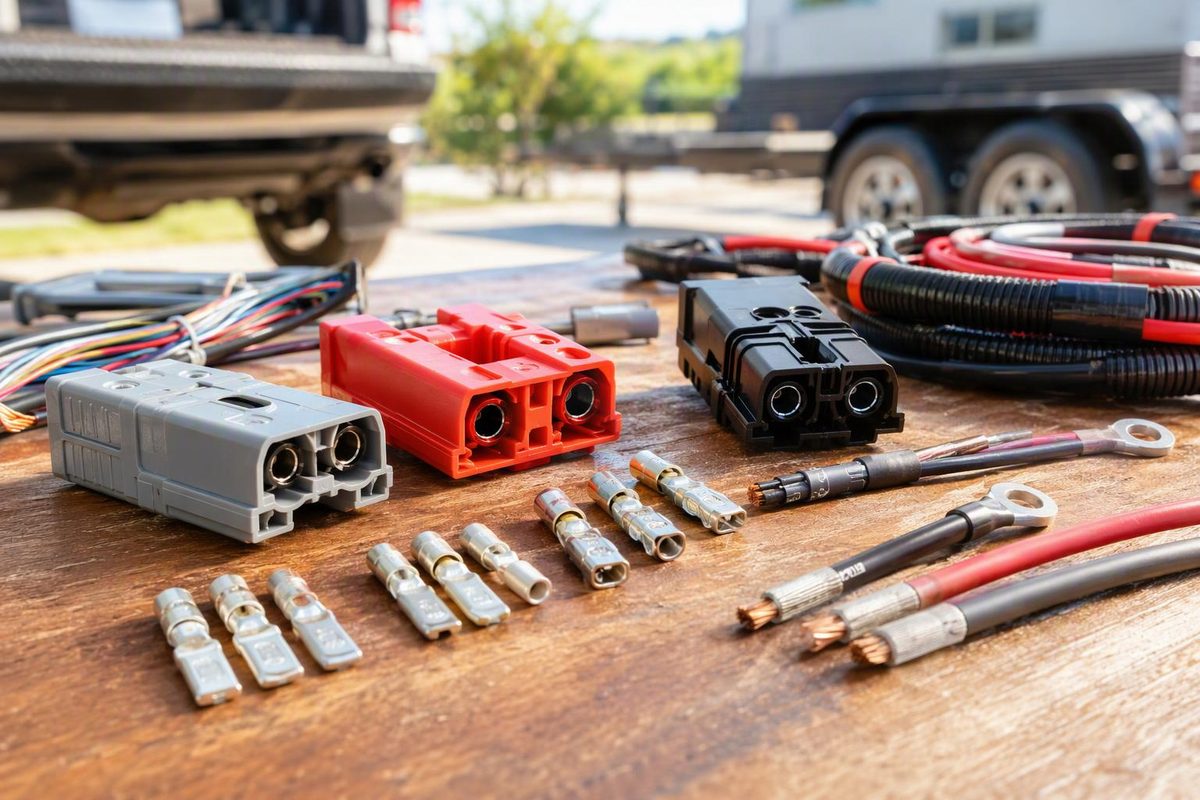
Match battery and cable connectors by conductor size first: PP15-type for 20–16 AWG light leads, PP30-type for 14–12 AWG, PP45-type for 10 AWG, and the SB50 family for 16–6 AWG two-pole battery leads. These are starting categories, not current ratings; the exact contact, wire construction, load, temperature, tooling and exposure control the final choice. Cable larger than 6 AWG generally calls for a larger SB family or another cable connector.
Choose the cable/use category and exposure; the selector gives the starting point and the check that can override it.
Connector Starting-Point Selector
Starting point
PP30-type contactFor a 14–12 AWG moderate accessory lead. Verify barrel fit, operating current and temperature before assembly.
Source: Anderson PP15-45 catalog, SB-series information and SB50 assembly instructions cited in the article. Categories are starting points, not load ratings.
| Cable And Use | Starting Point | Verify Before Assembly |
|---|---|---|
| 20–16 AWG (0.52–1.3 mm²), light accessory lead | PP15-type contact | Part number, wire construction and load |
| 14–12 AWG (2.1–3.3 mm²), moderate accessory lead | PP30-type contact | Barrel fit, current and temperature |
| 10 AWG (about 5.3 mm²), higher-current accessory lead | PP45-type contact | Part number, strand class, die and derating |
| 16–6 AWG (1.3–13.3 mm²), two-pole battery or equipment lead | SB50 family | Housing key, contact size, cable fit and current |
| Larger than 6 AWG | Larger SB family or another cable connector | Manufacturer selection table and tooling |
The familiar 15 A, 30 A and 45 A names do not give permission to load every contact to those values. Wire ampacity, voltage drop, contact construction, housing arrangement and operating temperature all remain part of the selection.
PP15, PP30 and PP45 Contacts Share One Housing
The familiar distributor breakdown is 20–16 AWG for 15 A contacts, 14–12 AWG for 30 A contacts and 10 AWG for 45 A contacts. All three use the same PP15-45 housing and mating interface, so the contact sizes intermate (Powerwerx).
The manufacturer’s contact table is more specific. Depending on barrel style, plating, mating force and conductor stranding, listed ranges include 20–16, 16–12 and 14–10 AWG. The PP15-45 family covers 20–10 AWG—0.75–6 mm² nominal in the catalog—and can reach 55 A per pole only under the stated conditions (Anderson PP15-45 catalog).
For example, the catalog lists 55 A for a single wire-to-wire pole with 10 AWG cable but 40 A for a fully loaded 3×3 wire-to-wire block using the same gauge. Those figures assume 105 °C-rated cable, recommended calibrated tooling and 25 °C ambient. Separate curves cover conductor size, ambient temperature and single- versus multipole layouts.
Size the wire for the load and acceptable voltage drop first. Then check the exact contact and connector configuration against the applicable curve. A kit advertised as “45 A” does not make its wire, fuse or completed harness suitable for 45 A. For the broader selection process, see Low Voltage Wire Connectors: How to Choose the Right Type.
Move to an SB Connector for Heavier Two-Pole Leads
PP15-45 works where compact individual poles or custom multipole arrangements are needed. Its housings have molded dovetails and can be stacked into a documented circuit layout.
For a heavier two-conductor battery lead, an SB connector is often the clearer fit. Anderson describes the SB line as two-pole, genderless DC-power and battery connectors. The series runs from SB50 through SB350 and uses color-coded, mechanically keyed housings; published ratings across the line extend from 50 to 500 A (Anderson SB series). Those family figures do not replace the rating for the selected housing, contact, cable and operating temperature.
SB50 has contact options for 16–6 AWG (1.3–13.3 mm²) stranded copper cable. One contact does not necessarily accept that entire range. Select the contact part number and any required reducing bushing for the actual conductor. Anderson’s assembly sheet specifies a 9/16 in (14 mm) strip length for SB50 and calls for recommended tooling (SB assembly instructions).
SB housing color is an identifier, not proof of voltage or polarity. Confirm the exact series and mechanical key on both halves. On an unfamiliar harness, determine polarity from documentation and measurement rather than insulation or housing color alone.
Crimp PP15-45 Contacts in the Correct Sequence
- De-energize the cable. Never terminate live conductors. A removable connector does not replace correctly selected circuit overcurrent protection; a fuse is designed to open under overload conditions (Littelfuse Fuseology guide).
- Set and record the housing layout. Assign positive, negative and any other circuits. Hold the two finished connector halves in their actual mating orientation and test-fit the empty housings before crimping. Genderless contacts allow identical halves to mate; they do not prevent a reversed-polarity layout.
- Match the wire, contact and tool. Check conductor gauge and strand class, contact part number, barrel style and specified die. In one documented 10 AWG open-barrel build, contact 261G2-LPBK is paired with Anderson tool 1309G3 (DigiKey). Other contacts may require another die or tool.
- Strip only to the barrel depth. Do not nick strands, leave bare copper behind the barrel or trap insulation in the conductor crimp.
- Crimp and inspect. Put every strand in the barrel. The contact must remain straight and narrow enough to enter the housing. A flattened, flared or bent barrel may not seat.
- Insert the contact until it locks over the spring. Tug the wire gently to confirm retention. Mate the pair, then verify polarity and continuity before connecting equipment. For a consequential load, also check voltage drop under representative current.
Anderson identifies only closed-barrel PP15-45 contacts as suitable for soldering. Do not add solder to an open-barrel crimp to compensate for the wrong contact or die (Anderson).
Standard PP15-45 Housings Are Not Environmentally Sealed
The standard PP15-45 housing has an open interface and is rated IP10 in Anderson’s catalog. Its finger-proof housing is IP20, a touch-protection rating, and does not mate with the standard housing. Neither rating establishes a sealed connection.
Anderson offers a splash boot for a 2×2 block but explicitly says it is not a hermetic seal (Anderson splash boot). Do not treat a standard PP15-45 connection as a sealed engine-bay, trailer-underbody or exposed off-road connector.
Where water or mud exposure is credible, select a connector system with a documented environmental rating, correctly fitted cable seals and plugs for unused cavities. Weather Pack connector selection and crimping covers one sealed option.
A finished connection must pass five checks: the housings mate, each contact fits its conductor, operating current remains within the applicable temperature curve, polarity is verified, and environmental exposure stays within the connector system’s documented protection.