
5 min read ·
Choose The Right Connector For Your Repair Or Harness
Match automotive connector housings, contacts and seals, compare six connector families, and check shared-return current before building an accessory harness.
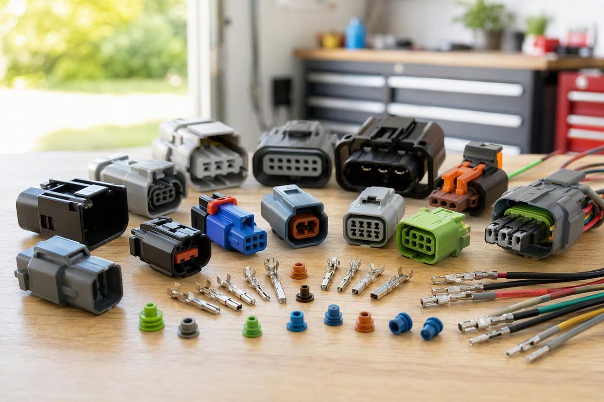
For a factory repair, match the original auto electrical connector and terminal specification. For a new accessory harness, select by current through each contact, wire fit, environment and service access. Contact count and a similar-looking housing are not enough to establish compatibility.
Enter two accessory currents and choose their return arrangement to screen the published family ratings.
Check Positive And Return Contact Current
Highest positive: 8 A. Shared return: 16 A. The shared return exceeds DT’s published 13 A continuous value.
Assumes both accessories run simultaneously, each through its own positive contact. “Within” means only within the published family value—not approved for your assembly.
Check exact terminals, wire fit, temperature derating, simultaneous loading and startup demand separately.
| Family | Published value | Positive screen | Return screen |
|---|---|---|---|
| DTM | 7.5 A | Exceeds | Exceeds |
| DT | 13 A | Within | Exceeds |
| DTP | 25 A | Within | Within |
| Weather Pack | 20 A | Within | Within |
| Metri-Pack 150 | 14 A | Within | Exceeds |
| Metri-Pack 280 | 30 A | Within | Within |
Rating Scope And Source Details
TE publishes DTM at 7.5 A per contact, DT at 13 A continuous per contact and DTP at 25 A continuous per contact. Legacy Delphi literature gives continuous maximum values of 20 A for Weather Pack, 14 A for Metri-Pack 150 and 30 A for Metri-Pack 280. These are not interchangeable assembly ratings.
Weather Pack’s application data include temperature derating and single-circuit, free-space limitations. The Metri-Pack catalog flags restrictions for certain thin-stock terminals. No installation-specific derating is calculated here.
Sources: TE DEUTSCH family pages and legacy Delphi Weather Pack and Metri-Pack catalogs linked in the article.
Treat the connection as a matched system: both housings, pin and socket contacts, wire seals, cavity plugs, secondary locks and crimp tooling. This guide covers low-voltage automotive wiring—not EV high-voltage connections or airbag-system repairs.
Identify The Original Connector Before Ordering
Record the vehicle’s year, model, engine and relevant equipment, then locate the connector in the applicable OEM wiring information. Follow the service procedure to isolate power before disconnecting or removing terminals. Photograph both halves before depinning.
Check these details against the replacement drawing:
- Full part number: include suffixes and keying codes, not just the family name.
- Mating geometry: latch position, guide ribs, cavity arrangement and polarization features.
- Contacts: pin or socket, mating dimensions, retention design and plating.
- Wire fit: conductor cross-section in mm² or AWG, plus insulation outside diameter in mm.
- Sealing and locks: individual cable seals or a rear grommet, interface seal, cavity plugs and required secondary locks.
Use the OEM connector identifier to connect the physical part to its circuit diagram. Ford’s 2015 Motorcraft identification guide, for example, describes using connector numbers to reach connector-face views and terminal part-number information in supported wiring manuals. A photo match alone cannot establish terminal compatibility.
If only a terminal is damaged, check whether an approved terminal repair is available before replacing the whole connector or harness.
Compare Published Ratings For A New Harness
These manufacturer family values help narrow the choice. The Weather Pack and Metri-Pack figures come from legacy Delphi literature; verify the current specification for the exact parts you order. These values do not establish allowable current for every contact, wire size or installation.
| Connector family | Published current value | Contact interface | Selection point |
|---|---|---|---|
| DEUTSCH DTM | 7.5 A per contact | Size 20 | Sealed, compact; lower-current connections |
| DEUTSCH DT | 13 A continuous per contact | Size 16 | Sealed accessory and equipment connections |
| DEUTSCH DTP | 25 A continuous per contact | Size 12 | Sealed; 2- and 4-cavity arrangements |
| Weather Pack | 20 A continuous maximum | Pin and sleeve | Individual seals; secondary cover lock |
| Metri-Pack 150 | 14 A continuous maximum | 1.5 mm blade | Sealed and unsealed variants |
| Metri-Pack 280 | 30 A continuous maximum | 2.8 mm blade | Sealed and unsealed; terminal restrictions |
Both Metri-Pack values come from the linked Delphi catalog. DEUTSCH contact size numbers are not wire gauges. Likewise, “150” and “280” identify Metri-Pack series associated with blade widths, not amperage ratings.
Do not treat these families as interchangeable. Match the exact mating pair and its approved contacts. For battery-size conductors or loads beyond these options, use the separate battery and cable connector guide.
Count Current In The Return Contact Too
List normal load current and relevant startup or inrush demand. Include the return path: it carries load current too.
Two accessories drawing 8 A each simultaneously through separate positive contacts put 16 A through one shared return contact. A DT contact published at 13 A continuous would not suit that shared return, even though each positive contact is below 13 A.
The calculator screens this arrangement against published family values; it does not calculate derating or approve a connector. Check the exact assembly’s temperature/current data, wire size and simultaneous loading conditions before selecting parts.
The linked Weather Pack application guidelines include temperature-derating curves and warn that their single-circuit, free-space data do not account for every installation variable. The Metri-Pack catalog also flags current restrictions for certain thin-stock terminals. The draft sources provide no universal derating factor to apply across these families.
Map The Pinout By Cavity, Not Wire Color
Before assembly, make a cavity-to-function list from the verified circuit diagram. Record power, return and signal functions separately.
Label every sketch with the connector half—harness or component—and whether it uses pin or socket contacts. State the viewing side: front mating face or rear wire-entry side. Show the orientation using the latch or another unmistakable keying feature.
Changing from front to rear view reverses the apparent layout. Copy the molded cavity numbers or letters; do not infer them by counting left to right. Two physically compatible housings can still be wired differently. Wire color is supporting identification, not proof of function. For an unknown factory lighting harness, see identifying tail-light wires by function.
Match The Seal And Crimp To The Wire
Conductor size determines terminal-barrel fit; insulation outside diameter determines seal fit. Verify both. The Weather Pack catalog lists separate conductor ranges for terminals and cable-diameter ranges for seals.
Buy tooling by terminal part number and construction—not merely a label saying “automotive crimper.” TE’s DEUTSCH common-contact instructions distinguish folded crimps for stamped-and-formed contacts from indent crimps for solid contacts, and require the recommended tooling. No added solder is required or recommended for either style.
During assembly:
- Follow the specified strip length without cutting strands, and fit cable seals in the sequence required by the terminal instructions.
- Inspect conductor insertion and the finished crimp against those instructions.
- Seat each contact fully and perform the specified retention check.
- Install secondary locks and the correct plugs in unused cavities.
- Support the harness so it does not pull on the wire entries.
TE’s common-contact instructions state that unused DEUTSCH cavities need correctly sized sealing plugs. The linked DT moisture specification applies to properly wired and mated connections—not loose halves or incomplete assemblies.
Test The Finished Connection Under Load
With power isolated and components disconnected as required by the service procedure, verify cavity mapping and check for unintended shorts. Then operate the circuit and measure voltage drop across the repaired connection using suitable access adapters.
A continuity beep alone cannot establish load-carrying performance. Fluke’s voltage-drop guidance explains that current must flow for the test to reveal circuit restrictions. Use the OEM’s limits rather than a universal pass/fail number.
Use correctly sized probes: Ford’s linked probe guidance warns that proper tip size reduces the risk of terminal damage. Follow the 12 V multimeter workflow to separate power-side and return-side losses.