
19 min read ·
How to Identify Every Rear-Light Wire Without Guessing by Color
There is no universal factory tail light wiring color code. Colors and pinouts can vary by year, make, model, trim, body style, market, production revision,…
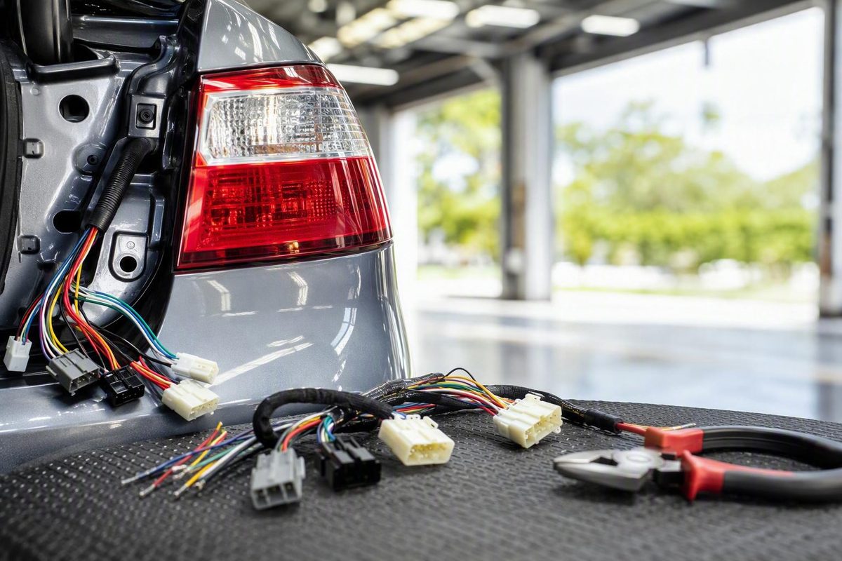
There is no universal factory tail light wiring color code. Colors and pinouts can vary by year, make, model, trim, body style, market, production revision, lamp side, connector, and harness section.
The dependable method is to identify the exact vehicle and connector, obtain the matching OEM wiring diagram and connector view, determine whether the stop and turn functions are combined or separate, and verify each pin using the vehicle’s prescribed electrical test procedure.
Do not cut, splice, repin, or pierce a rear-light wire solely because its insulation matches a generic color chart.
Why there is no universal factory tail-light color code
A single chart cannot reliably identify the rear-light wiring on every vehicle. The same manufacturer may use different colors across model years, production configurations, lamp sides, connectors, or sections of the harness. Replacement pigtails, prior repairs, aftermarket lamps, trailer converters, and supplier changes add further variation.
Manufacturer-level charts can help form a hypothesis, but they are not substitutes for service information tied to the exact vehicle and connector. Hitchweb’s generic and manufacturer-level guide, for example, says vehicle wire colors have changed over time and recommends testing the harness rather than relying on its tables alone (Hitchweb wire-color guide).
Reported patterns illustrate the problem:
- Black is reported as ground in several vehicle-specific examples.
- White is the conventional ground color in common four-way trailer wiring.
- Brown frequently appears as a tail or running-light feed in truck examples.
- Yellow and green commonly identify left and right stop/turn circuits in trailer wiring, but internal vehicle wiring may use them differently.
- In some seven-way trailer cables, black may carry auxiliary positive power rather than ground.
Color can help you trace an intact harness or locate a likely circuit. It cannot establish the function by itself. Connector cavity and measured behavior are more dependable observations:
- Useful: “Cavity 3 flashes with the left turn signal and is steady when only the brake is applied.”
- Unverified assumption: “The green wire must be the right turn signal.”
Treat a generic color table as a starting point to test—not as permission to alter the harness.
Identify the vehicle, connector, and type of harness first
Before looking for a diagram or testing a terminal, establish exactly what you are working on.
Use this intake checklist:
- Year
- Make
- Model
- Trim or equipment package
- Body style
- Market
- Production date, when available
- Left or right rear lamp
- Exact connector location
- Connector shape and cavity count
- Terminal-side or wire-side view
- Original, repaired, or replacement harness
- Factory or aftermarket trailer wiring
- Original or replacement lamp, socket, or pigtail
- Conventional bulb or LED assembly
“At the tail light” is not specific enough. Determine whether you are examining:
- The factory body harness
- A short factory lamp pigtail
- A removable bulb socket
- Wiring inside a lamp assembly
- A replacement pigtail
- A repaired harness section
- An aftermarket LED assembly
- A trailer converter or tee harness
- The vehicle side of a trailer connector
These sections can use different colors. A factory body-harness wire may pass through a connector and emerge as a different-colored replacement lead without changing function. Colors can also change at intermediate connectors.
Inspect the wiring before trusting what you see. Look for:
- Butt connectors, soldered joints, or repair sleeves
- Nonfactory tape or heat-shrink tubing
- Abrupt changes in wire gauge or insulation texture
- Replacement sockets with generic leads
- Empty, added, or repinned cavities
- Corrosion, damaged terminals, or discolored copper
- Water intrusion
- Crushed or stretched wiring
- Trailer wiring tapped into lamp circuits
- Paint, undercoating, oil, or dirt obscuring the insulation
Equivalent functions may use different colors on opposite sides. In a third-party report for a 2017 Hyundai Elantra, the left and right turn feeds were identified as blue/orange and red/orange, while the left and right tail feeds were identified as green/black and brown/black. The reported brake and ground colors were shared between the sides (2017 Elantra rear-light Q&A). This demonstrates possible side-to-side variation; it does not establish a verified pinout for every 2017 Elantra.
Before making a permanent modification, obtain as much of the following as possible:
- OEM wiring diagram for the exact configuration
- Connector identification number
- Connector face and cavity view
- Pinout
- Circuit names or numbers
- Splice and ground locations
- Fuse information
- Lamp or bulb configuration
- Control-module notes
- Manufacturer-prescribed diagnostic procedure
Use the latch, keyways, orientation marks, cavity numbers, and stated viewing direction rather than counting from an arbitrary corner.
The vehicle mappings later in this guide are third-party reports, not reproduced or independently verified OEM pinouts. They are included to demonstrate variation and evidence limitations, not to replace the correct service manual.
Before cutting anything, also check for a documented vehicle-specific adapter. In one first-generation Nissan Frontier discussion, the owner expected to splice differently colored aftermarket LED leads but later discovered that the assemblies connected through the original bulb sockets. No body-harness splice was needed (Nissan Frontier LED discussion).
Know which rear-light circuits you are trying to find
A rear-light connector may contain some or all of the following:
| Circuit | Behavior to confirm |
|---|---|
| Ground | Return path for one or more lamp functions |
| Tail/running | Active with the applicable parking or headlamp state |
| Brake | Active while the brake control is operated |
| Reverse | Active under the vehicle’s specified reverse-lamp test conditions |
| Left turn | Flashes with the left signal |
| Right turn | Flashes with the right signal |
| Side marker | Often follows the running-light state |
| License-plate feed | May follow the running-light state |
| Rear fog or market-specific lamp | Present only on applicable configurations |
Not every function will be present at every connector. A trunk-lid connector may carry only a subset of the rear-light circuits.
Do not assume that one positive wire powers every rear-light function. The cited Elantra report, for example, assigns distinct powered circuits to the brake, tail, turn, and side-marker lamps. Other architectures may differ, which is why the schematic must define what each connector input actually does.
Combined stop/turn systems
In a combined system, each side uses one circuit for both braking and signaling:
- Left stop/turn
- Right stop/turn
- Tail/running
- Reverse, if present at that connector
- Ground
Separate brake and turn systems
A separate system provides an independent brake feed and distinct turn-signal feeds:
- Brake
- Left turn
- Right turn
- Tail/running
- Reverse
- Ground
The brake and turn functions may use separate bulbs, separate LED sections, or different control inputs within the lamp.
This distinction matters when adding trailer wiring. A conventional four-way trailer harness uses combined left stop/turn and right stop/turn circuits. A vehicle with separate brake and turn outputs may therefore require a compatible converter or protected factory trailer output rather than direct wire-to-wire connections.
For the discussed 2007 Silverado, a third-party technician reported a separate light-blue brake feed at the rear and stated that the hazards used the turn-signal paths. The same answer described yellow and green trailer outputs as combined left stop/turn and right stop/turn circuits (Silverado technician Q&A). This is vehicle-specific third-party guidance without a reproduced OEM schematic or identified connector.
License-plate lighting may branch from a tail/running circuit. Participants discussing older GM square-body trucks reported that the rear harness fed both tail lamps and the license-plate lamp, with the plate lamp receiving the tail circuit. Confirm the arrangement on the exact vehicle rather than assuming that every plate lamp uses the same feed.
How to identify each wire with a multimeter or test light
Start with the exact connector view. Number every cavity according to the diagram. If no verified view is available, sketch the connector and mark its latch, keyways, empty cavities, wire-entry side, and orientation—but do not treat your sketch as a substitute for the OEM pinout.
Record findings by connector and cavity, not just by color:
Left rear lamp connector, Cavity 4 — appears brown/black — active with parking lights.
That record remains useful if the color was misread or the pigtail is later replaced.
Choose the test method from the service information
A third-party Chevrolet guide notes that newer vehicles may use body-control-module control or separate feeds that make lighting modifications more complex (Chevrolet truck verification guide). Use the meter, probe, breakout lead, scan tool, or other method specified for the exact circuit.
Obtain the correct procedure or use a qualified automotive electrical technician.
Before testing:
- Confirm the correct connector and viewing orientation.
- Inspect for corrosion, damage, or prior repairs.
- Use the prescribed reference point and meter setting.
- Keep probes from contacting more than one terminal.
- Avoid forcing probes into connector cavities.
- Follow the manufacturer’s instructions for powering, disconnecting, or reconnecting the circuit.
Screen a suspected ground
A continuity or resistance check can help screen a suspected ground, but it must be performed with power disconnected as required by the vehicle procedure. A reported Frontier test sequence similarly recommends checking continuity to ground before testing powered functions separately.
A basic screening process is:
- Follow the vehicle procedure for de-energizing the circuit.
- Select the prescribed meter mode.
- Connect to the specified chassis or circuit ground reference.
- Test the suspected ground cavity.
- Compare the reading with the schematic and diagnostic specification.
Never infer ground from black or white insulation. Either color may serve another purpose in a different harness.
If the result is unexpected, consult the schematic and use the manufacturer’s ground-circuit test rather than declaring the wire good.
Test powered functions one at a time
After establishing the prescribed meter mode and reference point, activate one function at a time. Record whether every pin is inactive, steady, flashing, or showing a measured value.
| Connector pin | Perceived color | All off | Parking on | Brake applied | Reverse test | Left turn | Right turn | Hazards |
|---|---|---|---|---|---|---|---|---|
| 1 | ||||||||
| 2 | ||||||||
| 3 | ||||||||
| 4 | ||||||||
| 5 |
Test these states separately:
- Everything off
- Parking lights on
- Brake applied
- Reverse-lamp test conducted under the manufacturer’s specified conditions
- Left turn activated
- Right turn activated
- Hazards activated
Do not perform a gear-selection test unless you can follow the vehicle manufacturer’s procedure and control the risk of vehicle movement. If the prescribed conditions or equipment are unavailable, stop and have the circuit tested professionally.
The expected observations are:
- A tail/running input changes with the applicable parking-light state.
- A dedicated brake input becomes steady when the brake is applied.
- A reverse input responds under the specified reverse-lamp test condition.
- A turn input flashes for the corresponding side.
A pin that flashes with the left turn signal and becomes steady when only the brake is applied may be a combined left stop/turn circuit. Repeat the observation on the right. If one separate pin responds to braking while the side-specific pins respond only to signaling, the system may use independent brake and turn feeds.
These observations still must be interpreted against the schematic. If readings are pulsed, ambiguous, dependent on connector state, or inconsistent with the diagram, do not assign the wire by guesswork.
Use the connector access method prescribed by the manufacturer. If the approved repair information calls for an invasive test, follow its specified restoration procedure.
If the chart and measurements disagree
Stop before making a connection. Check for:
- Wrong lamp side
- Wrong connector
- Reversed connector view
- Incorrect vehicle configuration
- Replacement or repaired pigtail
- Repinned terminal
- Corrosion or terminal damage
- Open or poor ground
- Production change
- Trailer converter or aftermarket module
- A test method unsuitable for the circuit
Keep the measured result as provisional. Do not splice until the connector identity, circuit architecture, and test result have been reconciled.
How to read striped wire colors and avoid visual mistakes
Automotive diagrams commonly identify a base color followed by a stripe or tracer. The separator may be a slash, dash, or another symbol defined in the manual.
Examples reported in the supplied vehicle discussions include:
| Notation | Reported meaning |
|---|---|
| VT/BK | Violet with a black stripe |
| DG/RD | Dark green with a red stripe |
| BR/R | Brown with a red stripe |
| L/R | Blue with a red stripe in the cited Nissan notation |
Always check the abbreviation legend in the exact manual. One manufacturer may reserve “B” for black and use “L” for blue, but those abbreviations are not guaranteed across brands.
Stripe order matters. A white wire with a black stripe is not the same written description as a black wire with a white stripe.
Appearance can be altered by:
- Road dirt or oil
- Fading and age
- Heat exposure
- Colored or dim shop lighting
- A narrow tracer visible on only one side
- Paint or undercoating
- Replacement wire
- Repairs hidden beneath loom or tape
Violet may appear nearly black. Brown may look orange or red. A narrow tracer may disappear into a dirty base color, and a striped wire can appear solid until rotated.
In the Frontier discussion, the owner described one wire as orange/red, while a participant reporting the manual notation interpreted it as brown/red. That disagreement is exactly why color must be checked against cavity position and electrical behavior.
Gently expose and clean only enough intact insulation to inspect it without damage. Examine the wire under neutral light and rotate it to find the tracer. Record both the observed color and the cavity:
Cavity 2 — appears orange/red; reported notation may be BR/R; function not yet confirmed.
If the observed color conflicts with the tested function, do not change the functional label merely to preserve the chart. Retain the cavity-based result provisionally, inspect for repairs or wire transitions, and obtain the correct connector information.
Vehicle-specific color examples—and their limits
The following are secondary, provisional reports—not verified factory pinouts. Connector identities, cavity orientations, production configurations, and original OEM diagrams were not available for confirmation. Use these examples to understand how much wiring can vary, not as a lookup table for making connections.
| Vehicle or range discussed | Reported mapping | Evidence and material limitation |
|---|---|---|
| 2007 Chevrolet Silverado | Brown: rear park/tail; light blue: brake; yellow: left turn; dark green: right turn; black: ground | Third-party technician interpretation. The connector and exact harness location are not identified, and no OEM schematic is reproduced. The page’s generated summary conflicts with the technician by calling the brake wire red; the technician’s answer says light blue. |
| 2017 Hyundai Elantra | Black: common ground; green: brake. Left: blue/orange turn, green/black tail, green/orange side marker. Right: red/orange turn, brown/black tail, green/orange side marker | Third-party expert Q&A. No VIN, market, trim, production date, or verified OEM connector view establishes applicability to every vehicle. |
| Certain 1973–1987 GM square-body trucks | Dark green: right stop/turn; yellow: left stop/turn; brown: tail/running; light green: reverse. Rear ground discussed as white or sometimes black | Forum reports covering multiple years and configurations. No factory diagram is reproduced (GM square-body discussion). |
| First-generation Nissan Frontier discussion | Black: ground; blue/red: tail; brown/red: brake/turn | A forum participant’s reported reading of a 2004 manual. The owner perceived brown/red as orange/red, and the final installation did not require splicing. |
| One owner’s 2001 Ford Ranger | Black: ground; brown: running; black/pink: reverse; orange/light blue: passenger turn; light green/orange: driver turn | Owner measurement. The owner inferred combined stop/turn operation, but these colors did not match the separate harness posted by the thread starter (Ranger owner-measurement thread). |
| Older Jeep Wrangler YJ examples | Violet/black: backup; black: ground; dark green/red: left turn; brown/red: right turn | Forum participants’ reported readings of service manuals. Black/yellow was disputed at the photographed connector and should not be assigned a definitive function (Wrangler YJ discussion). |
The GM discussion also illustrates the difference between body wiring and trailer wiring. Participants reported light green for reverse in the truck harness while noting that a conventional four-way trailer connection does not include a reverse circuit. They also discussed both white and black as possible rear-ground colors.
Assign evidence an appropriate weight:
- Exact OEM diagram and connector view for the vehicle’s production configuration
- Licensed service information tied to that configuration
- Verified manufacturer installation documentation
- A technician or participant reporting information from a manual
- Direct measurement on a similar vehicle
- Generic manufacturer-level chart
- Unsupported universal color claim
Even the correct diagram may not describe a harness that has been repaired, repinned, replaced, or modified. That is why documentation and testing should agree before the circuit is altered.
Factory body wiring is not trailer wiring
Trailer conventions describe a trailer harness or connector arrangement. They do not automatically identify wires inside the vehicle’s body harness.
A common four-way trailer-side color convention is:
| Trailer wire color | Conventional function |
|---|---|
| White | Ground |
| Brown | Tail/running |
| Yellow | Left stop/turn |
| Green | Right stop/turn |
A conventional four-way connection carries those four functions and does not include a reverse-light circuit. The GM square-body discussion specifically distinguishes its reported light-green truck reverse circuit from the functions available through a four-pin trailer connection.
The convention does not prove that the vehicle wire feeding a converter or trailer socket uses the same color. Internal vehicle wiring may use black for ground, a dedicated brake feed, different turn colors, or a separate reverse circuit.
Seven-way cable colors require even more caution. One third-party trailer chart reports the following assignments:
| Reported cable color | Reported function |
|---|---|
| White | Ground |
| Brown | Tail/running |
| Yellow | Left stop/turn |
| Green | Right stop/turn |
| Blue | Electric-brake output |
| Red or black | Auxiliary power |
| Purple | Reverse |
These are reported cable-color practices, not a guarantee that every seven-way product uses the same colors. The connector’s terminal functions, product documentation, and viewing orientation must be confirmed. If the documentation is unavailable, identify conductors from the defined connector terminals rather than assuming their purpose from insulation color.
The possibility of black carrying auxiliary positive power is a direct warning against treating black as an automatic ground.
When a vehicle has separate brake and turn feeds but the trailer has combined stop/turn lamps, an appropriate converter may be required. Some vehicles may instead provide protected trailer outputs. Determine the correct arrangement from the vehicle and converter manufacturers’ documentation rather than tapping whichever rear-lamp wire appears convenient.
Keep notes for each system separately:
- Factory body-harness cavity and color
- Lamp-pigtail cavity and color
- Converter input
- Converter output
- Vehicle-side trailer connector
- Trailer-side connector and cable
This prevents a trailer color convention from being mistakenly applied upstream to the vehicle’s lighting controls.
LED replacements, hyperflash, and mismatched aftermarket leads
There is no universal LED tail-light remedy. Compatibility depends on the vehicle, lamp design, connector pinout, polarity, flasher or control architecture, and product instructions.
Use this troubleshooting order:
- Confirm the exact application. Match year, model, body style, lamp side, and connector.
- Check for a documented plug-in adapter. Do this before considering a body-harness splice.
- Compare connector assignments. A physically matching plug does not establish the electrical function of every cavity.
- Verify polarity where the product requires it.
- Verify the ground circuit using the prescribed procedure.
- Test each vehicle input independently.
- Inspect sockets, terminals, pigtails, and prior repairs.
- Consult the lamp manufacturer’s instructions and vehicle service information.
- Only then evaluate a documented resistor, compatible flasher, converter, coding change, or other remedy.
LED replacements can present a lower electrical load than the incandescent lamps they replace. In some older turn-signal systems, that may be associated with rapid flashing, commonly called hyperflash. It does not follow that every LED conversion will hyperflash or that every rapid-flash complaint requires a resistor.
Load resistors and LED-compatible flashers are configuration-dependent possibilities, not universal repairs.
In the cited Wrangler YJ discussion, one owner reported that replacing both turn and hazard flashers with two-pin, time-based heavy-duty units eliminated the need for load resistors on one 1989 YJ. That is a single owner’s result on an older vehicle, not a general recommendation for other vehicles or body-controlled lighting systems.
Do not match aftermarket red, yellow, or black leads to factory wires by familiarity. Follow verified product instructions or test the assembly as directed. The Frontier example reinforces the value of inspecting the complete installation first: the replacement lamps ultimately connected through the original bulb sockets, so interpreting the loose lead colors and cutting the body harness were unnecessary.
Frequently asked questions
What color is the ground wire for factory tail lights?
There is no universal ground color. Black is reported as ground in several vehicle-specific examples, while common four-way trailer wiring uses white. Older GM discussions mention both white and black rear grounds, and other vehicles may use different colors.
Identify the exact connector and consult its diagram. Then screen and verify the suspected ground using the manufacturer’s prescribed de-energized test procedure. Neither black nor white insulation proves that a conductor is ground.
How do I tell whether brake and turn signals share the same wire?
Record each connector pin while operating the brake and turn functions separately.
If one side’s pin flashes with the turn signal and becomes steady when only the brake is applied, it may carry a combined stop/turn signal. Repeat the test on the opposite side. If a separate pin responds to braking while dedicated left and right pins respond only to signaling, the vehicle may use separate brake and turn circuits.
Confirm the interpretation against the exact schematic. Do not classify ambiguous or electronically controlled signals from color or a single meter observation alone.
What should I do when the wire colors do not match the diagram?
Stop before cutting or repinning. Confirm:
- Vehicle configuration and production information
- Connector identity
- Left or right lamp
- Terminal-side or wire-side view
- Cavity numbering
- Replacement pigtails or sockets
- Previous repairs
- Repinned terminals
- Corrosion or contamination
- Aftermarket lamps, converters, or trailer modules
Record the measured behavior by connector cavity and keep it provisional. Reconcile the discrepancy with the exact connector information before making a permanent connection.
Are factory tail-light colors the same as four-pin trailer wire colors?
Not necessarily. A common four-way trailer convention uses white for ground, brown for tail/running, yellow for left stop/turn, and green for right stop/turn. Internal factory wiring can use different colors, separate brake and turn feeds, or different pin assignments.
A conventional four-pin trailer connection also has no reverse-light circuit. Keep trailer conventions separate from the vehicle’s body-harness diagram.
Do LED tail lights always need load resistors?
No. Requirements depend on the vehicle, lamp, polarity, control architecture, and product instructions. Some older systems may flash rapidly after a lower-load LED conversion, while other installations may work without resistors.
Verify application, adapter availability, connector assignments, polarity, ground, and every input before changing a flasher or adding a resistor. If a resistor or other remedy is specified, follow the first-party installation and heat-management instructions.
Verify before you splice
- Identify the exact year, make, model, trim, body style, market, and production date.
- Determine whether you are testing the body harness, lamp pigtail, replacement assembly, repaired section, or trailer wiring.
- Obtain the exact OEM or licensed diagram, connector view, circuit labels, and fuse information.
- Confirm whether the diagram shows the terminal face or wire-entry side.
- Label every connector cavity.
- Verify the suspected ground with the circuit de-energized as prescribed.
- Test parking, brake, reverse, left-turn, right-turn, and hazard states separately.
- Record each pin as inactive, steady, flashing, or measured.
- Determine whether the stop and turn functions are combined or separate.
- Stop if readings are ambiguous or conflict with the diagram.
- Reconcile repairs, corrosion, production changes, and replacement components before altering the harness.
- Prefer a documented vehicle-specific plug-in adapter when one is available.
A wire’s color is a clue, not proof. Connector identity, exact service information, and verified electrical behavior should agree before you cut or splice.