
4 min read ·
Heat Shrink Solder Connectors: A Tight Sleeve Is Not Enough
Choose heat shrink solder connectors by wire fit and exposure, then verify solder flow and sealing. Compare solder sleeves with sealed crimp splices.
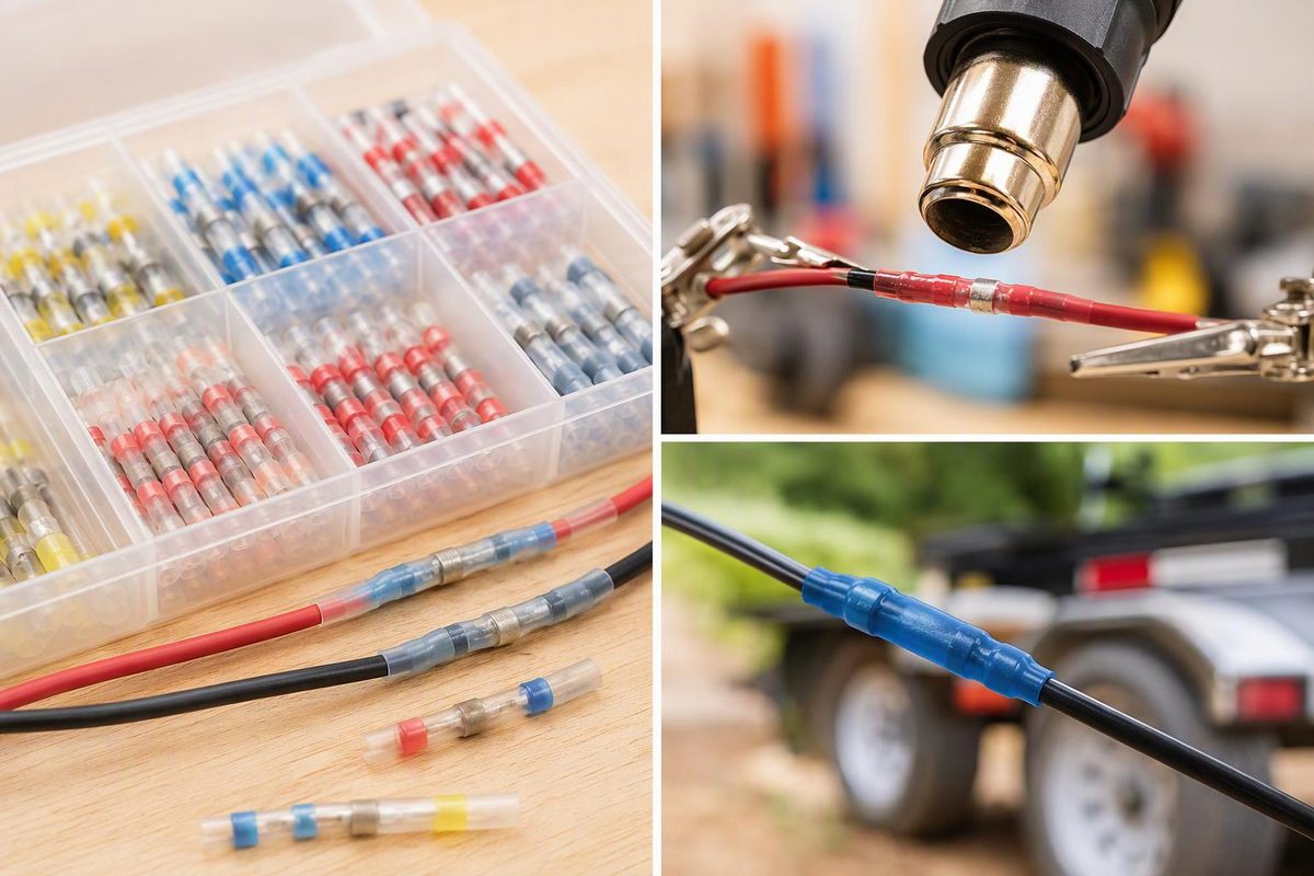
Heat shrink solder connectors make permanent wire splices using a preloaded solder ring inside a heat-shrink sleeve. A tight sleeve alone does not prove a sound connection: the solder must melt and form a bond between the conductors. TE Connectivity’s installation criteria distinguish an intact ring contour from an acceptable solder fillet—a visible formation of solder along the wire interface. TE installation procedure, sections 4.2.2–4.2.3
For automotive accessory and trailer wiring, choose a sleeve only when its documented wire compatibility, temperature limits and sealing performance suit the repair. “Solder seal” is a product description, not a universal waterproof or current rating.
Solder sleeve or heat-shrink crimp splice?
These are different joining methods, even when both have clear shrink insulation:
- Solder sleeve: Heat melts a fluxed solder preform to join overlapping conductors. Installation depends on correct positioning, heat delivery and visible solder flow.
- Adhesive-lined heat-shrink crimp splice: A metal barrel is crimped onto each conductor with the specified tool; heating then seals the insulation. Pacer’s procedure includes a gentle tug check after crimping, before applying heat.
- Conventional soldered splice plus separate tubing: Soldering and insulation are separate operations. Selecting suitable tubing does not establish whether the underlying splice method is appropriate.
The first two methods are described in TE’s wire-splicing catalog and Pacer’s butt-splice instructions.
For routine accessory repairs, a documented adhesive-lined crimp splice is a practical default when you have its matching crimper. Choose a solder sleeve when you can follow its preparation instructions and inspect the joint—not merely to avoid buying a crimp tool. Neither method excuses poor wire fit or unsupported wiring.
Factory-harness repairs are a separate decision. Follow the vehicle’s repair procedure rather than substituting a generic sleeve. For example, Honda’s 2013 Accord repair bulletin specifies special crimp-and-seal joints for listed repair pigtails and prohibits splicing airbag wiring. That is a model-specific requirement, not a rule for every vehicle. Honda Body Repair News, page 11
Match the wire and exposure before choosing color
Check the exact part number for:
- Conductor size and count on each side: Joining two wires to one requires an approved combination, not simply a larger sleeve.
- Insulation outside diameter: Both ends must fit within the sleeve’s sealing range. TE notes that strain relief depends on wire outside diameter.
- Conductor material and plating: Do not assume compatibility with aluminum or every copper-wire construction.
- Wire temperature rating and splice operating limit: These are separate specifications. A higher-rated sleeve does not raise the wire’s temperature rating.
- Required environmental protection: Splash exposure and immersion are different conditions.
TE’s catalog illustrates why similar-looking sleeves are not interchangeable:
| TE product series | Minimum wire temperature rating | Maximum splice operating temperature | Listed environment |
|---|---|---|---|
| B-155 / CWT | 85°C / 185°F | 125°C / 257°F | Splashproof |
| D-110 | 125°C / 257°F | 150°C / 302°F | Splashproof |
| D-1744 | 125°C / 257°F | 150°C / 302°F | Immersion sealed |
These are series-specific figures, not ratings for assorted solder-seal kits. TE catalog, page 7
For example, the D-1744 drawing specifies tin- or silver-plated conductors and a particular installation procedure. Its immersion capability is not permission to use it on any wire. TE D-1744 drawing
Use the manufacturer’s size chart rather than a universal red/blue/yellow rule. Also check circuit current, wire sizing and fuse protection independently; an AWG fit range is not, by itself, an ampere rating. For broader selection, see low-voltage wire connector choices.
Install without confusing shrinking with soldering
- Isolate power using the equipment’s service procedure. Confirm the circuit function before cutting; wire color alone is not proof.
- Prepare sound wire. Remove damaged sections and strip without cutting strands. Use the sleeve’s specified strip length and pretinning requirements—there is no universal preparation dimension.
- Overlap and center. Arrange the exposed conductors as instructed, with the solder ring centered over their overlap. Keep insulation within both sealing zones and prevent stray strands from puncturing the sleeve.
- Hold the assembly steady. Use a fixture that maintains wire alignment and sleeve position.
- Apply controlled heat with the specified tool and reflector. Work with ventilation, keep heat away from fuel and nearby vulnerable parts, and avoid charring. Continue to the manufacturer’s solder-flow endpoint, not merely until the tube becomes snug.
- Allow cooling before handling, then inspect and support the harness. Leave the repair free of tension and protect it from abrasion and repeated bending.
TE’s CWT/B-155 procedure specifies heat-gun or infrared equipment and warns that even its reference heat settings depend on reflector type and sleeve distance. Do not transfer one product’s setting or heating time to another. TE installation procedure
Inspect the solder, sleeve and finished circuit
For TE CWT/B-155 inline splices using the specified 9.5 mm strip preparation, the procedure requires at least 6.0 mm conductor overlap and a visible solder fillet at least 4.5 mm long. For wires requiring the 12.5 mm strip preparation and pretinning, the corresponding dimensions are 9.5 mm overlap and 8.0 mm fillet length. Wires with more than 19 strands require that second preparation, so strand count matters as well as gauge.
The solder must lose its ring appearance. Reject split or cut sleeves and strands poking through. These dimensions are not generic kit acceptance limits. TE preparation and inspection criteria, sections 4.2.1–4.2.3
Inspect both sealing ends against the product instructions before covering the splice. If the solder or seal cannot be verified, remake the connection rather than hiding it beneath another layer of tubing.
Finally, test the repaired circuit under its normal load. A continuity beep alone does not establish that a splice can carry operating current: Fluke explains that voltage-drop testing requires current flow and reveals restrictions that ordinary meter resistance tests can miss. Use accessible test points without puncturing the new seal, and compare results with the equipment’s service limits. Fluke voltage-drop guidance