
23 min read ·
Plan the Loads First, Then Choose the Control Panel
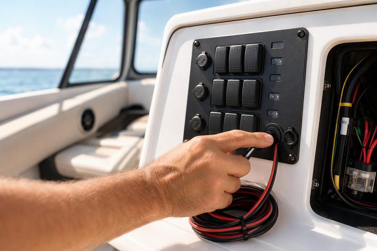
A 12V switch panel can organize the controls for lights, fans, pumps, compressors, heaters, horns, and other accessories. But the faceplate is only the visible part of the system. The electrical design behind it must account for the loads, switch functions, relays, conductors, circuit protection, return paths, connectors, operating environment, and consequences of failure.
Choosing by gang count or advertised switch amperage alone is risky. A rating printed on one switch does not establish the capacity of the panel’s common feed, internal bus, circuit board, jumpers, connectors, terminals, or supplied wiring.
This guide is a selection and installation-planning framework rather than a substitute for application-specific standards, manufacturer instructions, or a qualified electrical review. Start with a load inventory, decide which accessories may be switched directly and which require relay or contactor control, and then choose a panel whose complete ratings, schematic, dimensions, and environmental protection fit the installation.
What a 12V switch panel does—and what it may not include
A 12V switch panel is a centralized interface for controlling multiple low-voltage accessories. Common applications include cars, trucks, boats, RVs, campervans, trailers, race vehicles, ATVs, UTVs, and custom equipment.
The term “switch panel” can describe several substantially different products:
- Faceplate or modular housing: Holds separate switches but may include no wiring, fuses, or relays.
- Basic assembled panel: Includes switches in a plate, with the installer responsible for distribution, protection, and load wiring.
- Prewired panel: Includes some combination of positive jumpers, illumination wiring, or negative returns. “Prewired” does not necessarily mean that every outgoing branch is fused.
- Multifunction panel: Combines switches with USB charging, a voltmeter, a 12V socket, or other electronics.
- Fused switch panel: Places replaceable fuses in or near the panel, although the actual protection topology still needs inspection.
- Fuse-and-relay control box: Separates lower-current controls from protected accessory outputs.
- Electronic controller: Uses touch controls, programmable outputs, or wireless communication instead of conventional switches and discrete relays.
Seller catalogs illustrate how broad this category is. One catalog includes rocker, toggle, ignition, bilge-pump, and wireless panels in seller-listed configurations ranging from one to 16 gangs (DAIER switch-panel catalog). Other storefront listings add touch-controlled products, but catalog breadth does not establish that every panel shares the same electrical architecture or suitability.
USB chargers, voltmeters, 12V sockets, indicator LEDs, label backlighting, fuses, relays, and wireless receivers are optional. Confirm exactly which features are included, how they are wired, and whether they remain energized when the accessory switches are off.
Keep the following ratings separate:
- Individual switch-contact rating
- Per-circuit panel limit
- Common-feed or bus limit
- Connector and terminal limits
- Circuit-board or jumper capacity
- Supplied-conductor capacity
- Complete-panel combined limit
Those figures are component or seller claims, not proof that an assembled panel can carry the same current through every part of its shared path. Retail listings also show that visible titles and linked product specifications can conflict, reinforcing the need for a model-specific data sheet and schematic (True Mods switch and switch-box catalog).
Load type matters as well.
Treat descriptions such as “waterproof,” “marine-grade,” “heavy-duty,” and “certified” as vendor claims unless model-specific documentation defines the rating, test conditions, and covered parts. A seller’s product category can help identify available formats, but it does not validate an installation design.
Start with a load-planning worksheet, not a gang count
Before shopping, give every accessory and integrated electronic feature one row in a load worksheet. This converts “I need an eight-switch panel” into a usable electrical specification.
| Accessory or function | Control type | Continuous current | Startup or inrush | System voltage | Complete cable path | Switch limit | Relay assessment | Branch protection | Conductor selection | Environment | Consequence of shared failure |
|---|---|---|---|---|---|---|---|---|---|---|---|
| Front work lights | Maintained ON-OFF | From light documentation | From light documentation | Confirm operating range | Source, control/load, and return | From switch data sheet | Compare load with complete path | Calculate for conductor and load | Calculate for run and conditions | Exterior or wet area | Loss of work lighting |
| Water pump | As specified by pump maker | From pump documentation | Obtain if specified | Confirm | Include full return path | From switch data sheet | Assess motor behavior | Calculate | Calculate | Damp or vibration-prone | Loss of water system |
| Compressor | Maintained control, if specified | From compressor documentation | Obtain startup data | Confirm | Include relay-to-load path | Control-circuit rating | Assess relay or contactor | Calculate separately for load and control | Calculate | Heat and dust exposure | Loss of air system |
| USB converter | Always powered or switched | From converter documentation | Follow instructions | Confirm full range | Dedicated or shared feed as designed | Not applicable if separately fed | Usually a control decision | Calculate | Calculate | Cabin or dashboard | Standby battery draw |
| Spare position | Not yet assigned | Unknown | Unknown | Not yet established | Reserve routing only | Not yet established | Not yet established | Do not energize | Do not install as active branch | Intended future area | No active circuit |
Complete every field before installation. The panel listing is not the source for an accessory’s load current; use the accessory manufacturer’s documentation, including startup or inrush information where available.
If only power is stated, the basic relationship is:
I = P ÷ V
where current I is in amperes, power P is in watts, and voltage V is in volts. This is only a first estimate. A nominal 12V system does not remain at exactly 12 volts, and the calculation may not account for startup current, conversion losses, electronic control behavior, voltage drop, or device-specific instructions. The watts-divided-by-volts relationship appears in practical switch-panel discussions, but those discussions do not replace equipment data or installation standards (TinBoats wiring discussion).
Count functions only after defining them
Each independently controlled function generally needs its own switch position or electronic input. Add expansion deliberately. For example, six defined functions on an eight-gang panel leave two positions available for later use, but that is an illustration rather than a universal spare-capacity rule.
An unused position is valuable only if the enclosure, distribution hardware, connector count, feeder capacity, and future branch protection can accommodate another circuit. Do not pre-energize a spare wire for an unknown future load.
Distinguish switched accessories from integrated features:
- A voltmeter may have a separate positive and negative supply.
- A USB converter may remain powered unless deliberately switched.
- A 12V socket may require a separately protected branch.
- Label backlighting may be connected to a dashboard-illumination circuit.
- A status LED may be powered from the switch input or switched output.
- A wireless receiver or electronic controller may draw standby current while parked.
Calculate the maximum permitted simultaneous current on every shared positive segment and shared return. Do not total only the accessories you expect to use most often. Unless an interlock prevents simultaneous operation, the shared path must be assessed for combinations the controls allow.
Add a failure-priority column. If one common fuse opens or one shared terminal loosens, identify every function that will disappear. A shared failure affecting decorative lighting may be tolerable; a shared failure involving operationally important pumps, communications, navigation functions, or control circuits may not be. Separate functions where the consequences of one common failure are unacceptable, subject to the rules for the vehicle, vessel, or equipment.
Choose the switch function and panel architecture
A switch’s pole count describes how many electrically separate circuits it controls. Its throw count describes the available switching paths or selections.
Common arrangements include:
- SPST — single pole, single throw: Opens or closes one circuit. A maintained ON-OFF SPST switch suits straightforward single-function control.
- SPDT — single pole, double throw: Connects one common input to one of two outputs or paths.
- DPST — double pole, single throw: Operates two electrically separate ON-OFF circuits together.
- DPDT — double pole, double throw: Operates two changeover circuits together.
These configurations appear in retailer switch catalogs, but the exact terminal arrangement and electrical rating remain model-specific (Wiring Depot switch catalog).
A maintained switch stays in its selected position. A momentary switch returns when released. Momentary control is appropriate when the device should receive a command only while the operator holds the switch, but the accessory documentation must define the intended behavior. Do not substitute a maintained switch simply because it fits the same opening.
Terminal count and physical resemblance do not prove function. Three terminals might belong to an illuminated SPST switch, an unilluminated SPDT switch, or another arrangement. Two switches with identical bezels can have different contact functions, LED circuits, or internal jumpers. Verify the exact part number, continuity diagram, and illumination schematic.
Comparing panel architectures
| Architecture | Wiring effort | Flexibility | Common-failure exposure | Serviceability | Questions to resolve |
|---|---|---|---|---|---|
| Basic rocker or toggle panel | Moderate; installer creates distribution and protection | High | Depends on feeder design | Usually good if switches are replaceable | Are complete-path ratings documented? |
| Modular housing | Highest assembly effort | Very high | Installer-controlled | Individual parts may be replaceable | Will matching switches and blanks remain available? |
| Prewired multifunction panel | Lower initial assembly effort | Moderate | Shared jumpers may create common failures | Varies | Can USB, socket, voltmeter, and switch feeds be separated? |
| Fused switch panel | Moderate | Moderate | Depends on internal bus topology | Good if standard fuses remain accessible | Does each fuse protect an actual outgoing branch? |
| Fuse-and-relay box | Keeps accessory current away from dashboard controls | High | A common feed or module may affect several outputs | Good if relays and fuses are replaceable | Are load type, relay, connector, and output limits documented? |
| Programmable or wireless controller | Potentially simpler field wiring | High logical flexibility | Module failure may affect all outputs | Often dependent on proprietary parts | What are standby draw, override behavior, and replacement options? |
There is no universal winner. Conventional switches are comparatively transparent to inspect and diagnose, but they require more discrete wiring. Prewired panels reduce initial assembly work, yet undocumented jumpers can complicate protection. Relay boxes keep accessory current out of the dashboard.
Treat a high-current master disconnect as a separate design problem. In regulated racing or commercial applications, the disconnect type, accessibility, labeling, operation, and placement may be controlled by a current rulebook. Consult that rulebook and a qualified reviewer rather than copying a forum layout or accessory-panel arrangement.
Decide between direct-load switching and relay control
There are two basic functional paths.
Direct-load switching:
Source → source/branch protection → panel switch → low-current load → return
Relay-controlled switching:
Load path:
Source → load-circuit protection → relay contacts → accessory → return

Control path:
Protected control feed → panel switch → relay coil → control return
These diagrams show circuit functions. They are not universal instructions for terminal numbers, wire sizes, or fuse values.
When direct switching can work
Direct switching is an option only when the accessory’s documented continuous and startup currents remain within the verified limits of the entire current path:
- Source protection
- Feed conductor
- Panel bus or jumper
- Switch contacts
- Terminals
- Connectors
- Output conductor
- Return path
The lowest valid limit governs. A switch rated above the panel’s common bus does not increase the bus capacity. Substantial-looking switch bodies also do not validate thin, undocumented jumpers or connectors.
Direct switching is most straightforward for verified low-current loads. Even then, assess the load type, startup behavior, voltage drop, environmental conditions, and termination ratings rather than relying on nominal wattage or switch-face markings alone.
When to consider a relay or contactor
A correctly selected relay or contactor allows the panel switch to carry control or coil current while the accessory current follows a separate protected load path.
Verify all of the following:
- Contact voltage and current ratings
- Suitability for the actual load type
- Coil voltage and coil current
- Continuous or intermittent duty
- Accessory startup or inrush current
- Load-side conductor and protection
- Control-side conductor and protection
- Terminal and connector limits
- Environmental sealing and mounting instructions
Do not select a universal “30A relay” merely because that size is common.
Several relay coils and indicator LEDs may share one protected control feed if the feeder, terminals, return, and overcurrent protection are assessed for their combined current. Practical automotive discussions describe this arrangement while also emphasizing that accessory load circuits remain separately protected; those discussions are examples, not standards or model-specific instructions (NAXJA relay-control discussion).
A shared control feed reduces wiring but creates a common failure point. One open fuse, broken conductor, or loose terminal can disable every control connected to it. Keep the control-circuit protection conceptually and physically distinct from the accessory load-circuit protection. A small control fuse cannot protect a lamp, pump, or compressor supplied by a separate high-current path.
Plan the main feed, branch fuses, bus, and negative return
A conventional planning architecture is:
Battery or source
    ↓
Source-side main protection
    ↓
Positive distribution point or fuse block
    ↓
Individually assessed and protected branches
    ↓
Switch contacts or relay contacts
    ↓
Loads
    ↓
Negative bus or other approved return path
    ↓
Source negative
A central fuse block accepts one source input and distributes power to multiple protected circuits. This can simplify labeling, service, expansion, and fault isolation. Some blocks also provide a negative bus, but the return conductors and bus feeder still require a combined-current assessment. Manufacturer guidance describes the general battery-to-main-protection-to-fuse-block arrangement, but it does not supply universal conductor or fuse values (DAIER fuse-block guide).
As a planning principle, overcurrent protection must be coordinated with the connected conductor and the accessory manufacturer’s instructions. Exact fuse and conductor selections depend on load current, startup behavior, cable length, acceptable voltage drop, conductor material and insulation, bundling, routing, temperature, termination ratings, and the rules applicable to the platform.
Do not copy a generic conductor or fuse example from a product page. Instead, use this bounded workflow for each branch:
- Obtain the accessory’s documented continuous and startup current.
- Identify the complete positive and return cable path.
- Select the circuit architecture: direct switching or relay control.
- Apply the relevant automotive, marine, RV, equipment, or motorsport guidance.
- Select a conductor for the current, run length, voltage-drop target, insulation, routing, bundling, and temperature.
- Select branch protection that coordinates with that conductor and respects the accessory instructions.
- Confirm that every switch, relay, terminal, connector, bus, and jumper in the path supports the resulting circuit.
- Recalculate every shared feeder and return for maximum permitted simultaneous operation.
- Record the result in the wire-and-fuse schedule.
Place source-side protection according to the applicable standards, platform guidance, and component instructions. There is no single battery-distance figure appropriate for every vehicle, vessel, cable route, or source arrangement.
Three ways to distribute switch power
1. Daisy-chained feed
One feed enters the first switch, and jumpers continue from switch to switch.
Advantages:
- Fewer home-run conductors
- Compact layout
- Potentially useful for correctly assessed, low-current relay coils and indicator circuits
Tradeoffs:
- Upstream links carry the combined downstream current
- A loose early connection can disable later controls
- Voltage drop and heating can accumulate across connections
- One fuse may create a broad failure domain
- Individual branch protection may be absent
Do not treat an unfused daisy chain as a general solution for directly switched accessory loads.
2. Common bus with separate branches
One appropriately rated feeder supplies a bus, and separate conductors leave the bus for individual switch or control branches.
Advantages:
- Clearer branch organization
- One branch connection is less likely to interrupt others
- Easier current accounting than a serial jumper chain
- Compatible with individual branch protection
Tradeoffs:
- The feeder and bus still carry combined current
- Bus rating, covers, spacing, and mounting must suit the environment
- A common feeder or bus failure can still disable all branches
3. Individually protected feeds
Each switch circuit or relay-control circuit receives a separately protected feed from a fuse block.
Advantages:
- Improved fault isolation
- Protection can be coordinated with each branch
- Straightforward labeling and troubleshooting
- Easier separation of operationally important circuits
Tradeoffs:
- More wiring and terminations
- Greater fuse-block and harness requirements
- More installation space and planning
Some prewired panels use a daisy-chained positive feed without individual branch protection. Depending on the actual topology, obtaining separately protected branches may require inline branch fuses or replacement of the common jumper with individual feeds from a fuse block. A campervan wiring guide describes both approaches for the panels it covers, while cautioning that the exact panel pinout remains model-specific (campervan switch-panel wiring guide).
Do not overlook the return path
Current must return to its source. A shared negative conductor, negative-bus feeder, daisy-chained LED return, or shared connector contact must therefore be assessed for the maximum combined current that can flow through it.
Do not assume that a conductor labeled “ground” carries negligible current. Indicator LEDs may draw little, while accessory returns can carry the full load current. Keep low-current illumination returns conceptually separate from high-current load returns, and verify whether the platform permits chassis return, requires dedicated conductors, or imposes application-specific bonding rules.
Decode illumination and multifunction wiring without guessing pins
A basic two-pin SPST circuit generally has two switching connections:
- Protected positive input
- Switched output to the load or relay coil
The load or relay coil then has its own return path.
An illuminated three-pin SPST switch commonly adds a negative or return connection for its LED. That arrangement is common rather than universal. A three-terminal device could instead be SPDT, and manufacturers can wire illumination differently.
Five-pin rocker switches often separate two lighting functions:
- Backlighting: Makes the label visible when the dashboard or panel lights are on.
- Status indication: Illuminates when the controlled accessory is active.
That separation allows the label to be visible without falsely showing that the load is operating. One manufacturer’s guide assigns numbered terminals to the input, output, LED returns, and optional dashboard illumination, but those assignments apply only to the documented switch arrangement and must not be treated as a universal pinout (DAIER five-pin rocker-switch guide).
Integrated devices may be separate circuits
A USB converter, voltmeter, or 12V socket may have its own positive and negative conductors. Determine:
- Whether it is always powered or switched
- Its supported operating-voltage range
- Its continuous and standby current
- Whether it contains internal protection
- What external protection its supply conductor requires
- Whether its negative is internally shared
- Whether any environmental rating applies with covers open or closed
Do not assume that the switch-panel feed protects every integrated device appropriately. A socket intended to supply an external plug-in load may impose substantially different requirements from the panel’s indicator LEDs.
Check each subsystem.
Inspect a prewired panel before energizing it
Before connection:
- Obtain the model-specific schematic.
- Photograph the rear of the panel.
- Trace every jumper and label both ends.
- Identify all common positive and negative paths.
- Identify each switched output.
- Separate backlighting from status illumination.
- Identify the feeds for any voltmeter, USB converter, or socket.
- Perform continuity or resistance checks only with the circuit de-energized.
- Use the correct energized voltage or polarity setting and appropriate safeguards if live testing is necessary.
- Confirm that supplied wire colors agree with the documentation, without relying on color alone.
Use terminals compatible with the switch blades, studs, or connector system. Crimp with the appropriate tool, insulate exposed conductive parts, support the harness, and provide strain relief so vibration or dashboard removal does not pull on the electrical contacts.
A sealed connector can improve serviceability in an exposed detachable harness when its current rating, conductor range, cavity count, and environmental specification suit the circuit. Install unused-cavity plugs where required and match conductor-insulation diameter to the rear seal. Plug It Right’s Deutsch DT assembly guide explains contact crimping, seating, and unused-cavity sealing for that connector family; it does not establish that Deutsch DT is mandatory or suitable for every switch-panel circuit.
Verify fit, environment, documentation, and serviceability before buying
A panel can be electrically appropriate but impossible to install or service. Measure the actual location before ordering.
Measurement checklist
Record:
- Dashboard cutout width and height
- Outer bezel width and height
- Corner radius, where relevant
- Fastener locations and edge clearances
- Mounting depth behind the face
- Depth with terminals and connectors installed
- Clearance for straight or right-angle terminals
- Cable bend space and harness exit route
- Room for strain relief and harness supports
- Visibility from the operating position
- Clearance from steering and other controls
- Switch access while wearing gloves, if relevant
- Room to remove individual switches
- Access for fuse and relay replacement
- Clearance from heat sources and moving mechanisms
A cutout dimension alone is insufficient. Rear terminals and stiff cables add practical depth, and a connector that fits before dashboard assembly may become impossible to unplug afterward.
Evaluate the whole environmental boundary
For wet, dusty, corrosive, or vibration-prone installations, inspect:
- Face seals and switch boots
- Rear-terminal covers
- Connector seals
- USB and socket caps
- Bezel and mounting-hole sealing
- Corrosion-resistant terminals and hardware
- Harness supports and strain relief
- Drainage and installation orientation
- Protection from spray, abrasion, and conductive debris
It may not cover rear terminals, open USB ports, sockets, connectors, mounting penetrations, or the assembled dashboard. Ask for the model-specific test scope rather than treating “waterproof” as a property of the entire installation.
Documentation to request
Before buying, obtain written, model-specific information for:
- Complete-panel continuous current
- Complete-panel peak or transient limits, if applicable
- Per-circuit limits and load-type qualifications
- Common-feed and bus ratings
- Relay contact and coil specifications
- Fuse type and ratings
- Supplied conductor sizes and insulation specifications
- Connector type and terminal limits
- Supported voltage range
- Cutout, bezel, depth, and fastener dimensions
- Environmental-rating scope and installation conditions
- Certification documents, if claimed
- Full wiring schematic
- Standby current
- Replacement switches, fuses, relays, labels, and harness parts
Buying red flags
Pause when a listing has:
- No schematic
- Only individual-switch amperage
- No complete-panel or bus rating
- Vague “marine” or “waterproof” wording
- No dimensions or rear-clearance drawing
- Conflicting specifications between the title, description, and URL
- Reviews aggregated across multiple variants
- No replaceable-component information
- No explanation of fuse or relay access
- No standby-current figure for an electronic controller
- No useful response to technical questions
Marketplace breadth, low prices, and review counts do not resolve missing engineering information. Seller listings can demonstrate that basic housings, multifunction panels, and electronic relay systems exist, but they cannot establish model-specific safety, durability, or suitability without supporting documentation.
Install, inspect, and troubleshoot methodically
Begin with three documents:
- The finalized load worksheet
- The panel’s model-specific schematic
- A wire-and-fuse schedule whose labels match the installation
Before wiring, disconnect the battery or power source’s negative terminal according to the vehicle, vessel, battery-management, memory-retention, and equipment manufacturer’s procedures. Manufacturer rocker-switch guidance also calls for disconnecting the negative terminal before electrical work, but the platform procedure takes priority.
Build the harness with secure, correctly crimped terminals. Support it so vibration and service movement do not pull on contacts. Protect rear terminals from accidental shorts, provide strain relief, label both ends of each conductor, and cover exposed distribution hardware.
Pre-power inspection
Before reconnecting power, verify:
- Terminal identity against the schematic
- Correct polarity
- Source-side protection
- Every required branch-protection device
- Protection values against conductor selections and load instructions
- Shared-feed combined capacity
- Shared-return combined capacity
- Separation of relay control and contact circuits
- Connector seating and secondary locks
- Insulation around exposed terminals
- Harness support and abrasion protection
- No likely short to the panel, dashboard, or chassis
- Unused outputs are insulated and secured
Commission one circuit at a time. For each circuit, check:
- Correct switch operation
- Correct backlight and status-indicator behavior
- Voltage at the load while operating
- Connector and terminal security
- Relay operation, where used
- Unexpected voltage drop
- Unexpected heating after a representative operating period
Troubleshooting table
| Symptom | Checks |
|---|---|
| Load is dead | Check source protection, branch protection, switch input and output, relay control and contact paths, load return, connector seating, and the load itself. |
| Load works but switch LED is dark | Verify the model-specific illumination return, LED polarity, pinout, and whether the indicator is intended to follow the switched output. |
| Label is always lit | Determine whether the conductor powers backlighting rather than status indication and whether it was connected to constant power instead of the intended illumination circuit. |
| Fuse repeatedly opens | Disconnect the circuit. Inspect for a short, damaged insulation, reversed connections, incorrect load data, startup or inrush current, unsuitable protection assumptions, or overloaded wiring. Do not increase the fuse solely to stop it opening. |
| Switch or terminal becomes hot | Shut down immediately. Check measured current, startup behavior, terminal fit, crimp quality, contact resistance, conductor selection, complete-panel ratings, and whether relay control is required. |
| Several controls are dead | Check the shared feed, common fuse, bus connection, electronic controller, and shared return. |
| Relay clicks but load remains off | Check the separately protected load feed, relay contact path, output conductor, connector, and load return. |
| Accessory works intermittently on rough roads | Inspect terminal retention, connector locks, harness supports, crimps, abrasion points, and switch mounting. |
Successful operation does not prove that the installation is safe. A circuit can function while a terminal is loose, a conductor is inadequately protected, voltage drop is excessive, or a shared feed is overheating. Complete the protection, temperature, voltage-drop, polarity, and mechanical inspection after functional testing.
Obtain qualified, application-specific review when panel ratings are missing, calculations remain uncertain, high-current equipment is involved, safety-critical functions share a circuit, or automotive, marine, RV, commercial, or motorsport requirements apply.
Can I connect several 12V panel switches to one power feed?
Yes, conditionally. A shared feed may be practical for low-current relay coils, indicator LEDs, or similar control circuits when the feeder, jumpers, terminals, return, and overcurrent protection have been assessed for maximum combined current.
The tradeoff is a common failure point: one open fuse, loose upstream terminal, or failed conductor can disable every connected control. Do not assume a factory daisy chain can carry the sum of the individual switch-face ratings.
Does every accessory on a switch panel need its own fuse?
The protection arrangement depends on the circuit architecture, conductors, load instructions, and applicable requirements. In many accessory systems, separately protected branches improve fault isolation and allow each branch to be coordinated with its conductor and load.
One main protective device does not, by itself, establish that every smaller downstream conductor is suitably protected. Related low-current control devices may share a protected circuit after a combined-current and failure-consequence assessment. Integrated USB ports, voltmeters, and 12V sockets may also require protection independent of the switched accessory branches.
When does a 12V accessory need a relay?
Consider a relay or contactor when continuous current, startup current, load type, electrical noise, manufacturer instructions, or the panel’s complete-path limits make direct switching unsuitable.
Motors, pumps, compressors, solenoids, winch controls, and some lighting electronics deserve particular scrutiny. Select the relay by its contact rating for the actual load, coil voltage and current, duty, environment, conductors, protection, terminals, and connectors—not by a generic headline amperage alone.
What is the difference between a two-pin, three-pin, and five-pin rocker switch?
A two-pin SPST rocker commonly provides protected input and switched output. A three-pin illuminated SPST rocker commonly adds an LED-negative connection, although a three-terminal switch can instead have another function, such as SPDT.
A five-pin illuminated rocker often separates label backlighting from an “accessory on” indicator in addition to the switching contacts. These are common arrangements, not universal standards. Confirm the exact continuity and illumination diagrams instead of relying on pin count, position, numbering, or wire color.
Is a waterproof or marine switch panel waterproof behind the dashboard too?
Not necessarily. A waterproof or IP-rated face does not automatically mean the rear terminals, connectors, USB ports, sockets, cable entries, fastener holes, or dashboard cutout receive the same protection.
Ask which surfaces and components the rating covers and under what installed conditions. In exposed locations, assess rear-terminal protection, compatible sealed connectors, strain relief, harness support, corrosion-resistant hardware, orientation, drainage, and sealing around mounting penetrations.
Go/no-go checklist
Proceed only when every answer is yes:
- [ ] Every load and integrated electronic feature is inventoried.
- [ ] Continuous current is known from reliable, model-specific documentation.
- [ ] Startup or inrush current has been addressed.
- [ ] Direct switching or relay control is justified for each circuit.
- [ ] Complete-path ratings—not only switch-face ratings—are documented.
- [ ] Source and branch protection are planned under the applicable guidance.
- [ ] Protection choices coordinate with the conductors and respect load instructions.
- [ ] Shared positive feeds are assessed for maximum combined current.
- [ ] Shared returns are assessed for maximum combined current.
- [ ] The consequences of a common fuse, feed, bus, or connection failure are acceptable.
- [ ] The model-specific schematic is available.
- [ ] Integrated electronics support the actual system-voltage range.
- [ ] Cutout, bezel, mounting depth, connector clearance, and cable bend space are confirmed.
- [ ] Environmental protection includes rear wiring and mounting penetrations, not only the face.
- [ ] Fuses, relays, connectors, and switches remain accessible for service.
- [ ] Applicable vehicle, vessel, equipment, and motorsport requirements have been checked.
If any safety-critical rating or installation requirement remains unknown, pause the purchase or installation. Obtain model-specific manufacturer documentation or qualified, application-specific guidance rather than designing around an assumption.