
21 min read ·
How to Identify and Wire an Illuminated Rocker Switch Without Guessing the Pins
In the common verified example, fused positive goes to pin 2, pin 3 feeds the accessory or relay, and the accessory negative uses an approved return.
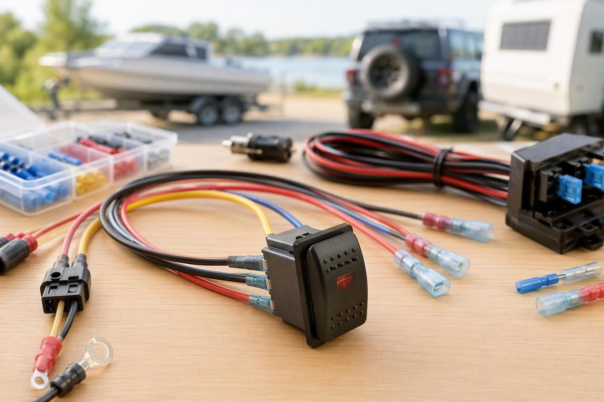
Start Here: Five Pins Do Not Mean One Universal Pinout
Scope: This guide covers low-voltage DC accessory circuits, particularly 12 V automotive, RV, trailer, marine, and off-road installations. It is not a household mains-wiring guide and must not be adapted to residential AC power.
A “5-pin rocker switch” is a category, not a complete wiring specification. Five terminals tell you how many external connections exist; they do not establish the terminal order, numbering, physical orientation, internal LED arrangement, current rating, or grounding scheme. The exact schematic or verified terminal mapping must control because pin count alone does not establish a universal pinout (Nassau National Cable’s rocker-switch wiring guide).
An illuminated ON-OFF rocker commonly combines three functions:
- Mechanical switch contacts: One terminal receives power, and another sends switched power to an accessory or relay.
- ON-state indicator: An LED illuminates when the rocker or controlled circuit is active.
- Locator or dashboard backlight: A separate LED illuminates the label so the switch can be found at night.
Those functions can be connected internally in different ways. A switch may have separate LED negatives, one common negative, or an internal link that changes what an external terminal does. A diagram can therefore resemble your switch while still being electrically wrong for it.
The critical conflict involves pins 7 and 8 on the frequently encountered 2-3-6-7-8 arrangement. The documented Switch Boss variant connects both pins 7 and 8 to negative, while Daier’s illustrated variant connects pin 7 as the common LED ground and leaves pin 8 without an external connection because of an internal link (Switch Boss’s five-pin instructions; Daier’s illustrated five-pin guide).
Therefore:
The manufacturer’s part-specific diagram, terminal markings, and datasheet take precedence over every example below. Do not connect battery power until you have positively identified the mechanical contacts and LED terminals.
If the part cannot be identified confidently, replace it with a documented switch. Do not use unrestricted battery power to discover what an unknown terminal does.
Quick-reference diagram: common example, not universal
COMMON 2-3-6-7-8 FUNCTIONAL EXAMPLE

Fused positive supply --------------> Pin 2: power input
Pin 3: switched output -------------> Accessory positive or relay trigger
Accessory negative -----------------> Approved negative return
Dash-light positive, optional ------> Pin 6: backlight positive
Pin 7 ------------------------------> Verify model-specific LED function
Pin 8 ------------------------------> Verify; may be ground or externally unused
This is a functional summary, not a rear-terminal position map. Verify the exact switch before translating these labels into blade locations.
The Common 2-3-6-7-8 Layout and What Each Connection Does
The following arrangement recurs on several illuminated 12 V rockers. It is a useful working example, but it is not an industry-wide standard.
Common example, not universal
| Pin | Common example function | Typical external connection |
|---|---|---|
| 2 | Positive power input | Correctly fused positive supply |
| 3 | Switched positive output | Accessory positive or relay-coil trigger |
| 6 | Optional backlight positive | Dash-light positive, another documented supply, or no connection |
| 7 | Model-dependent LED connection | Often LED negative or common ground; verify |
| 8 | Model-dependent LED connection | May be another LED negative, internally linked, or externally unused; verify |
On this recurring layout, pin 2 supplies the mechanical switch and pin 3 becomes live when the rocker is ON. Pin 6 supplies the optional locator or dashboard illumination. Documented instructions for this configuration identify pin 2 as input, pin 3 as output, and pin 6 as the optional backlight supply (Switch Boss’s five-pin instructions).
Pins 7 and 8 must remain model-dependent in any responsible 5 pin rocker switch wiring diagram. Even sources that agree about pins 2, 3, and 6 disagree about the two LED connections. Do not assign universal “upper LED” and “lower LED” functions to those numbers.
In plain language, the mechanical portion controls whether power reaches the accessory. The extra terminals generally support the rocker-face backlight and ON indicator; they do not automatically form additional load-carrying switch contacts.
Labeled functional schematic
The diagram below deliberately avoids arranging the terminals in a physical pattern. Read it as a list of functions, not as a view of the switch’s rear face.
COMMON 2-3-6-7-8 EXAMPLE — VERIFY YOUR SWITCH FIRST

12 V DC positive
      |
      +---- correctly selected fuse ----> [Pin 2: POWER INPUT]
                                             |
                                      internal ON-OFF contact
                                             |
                                          [Pin 3]
                                             |
                           accessory positive OR relay trigger

Accessory negative ----------------------> approved negative return

Dash-light positive or another
documented illumination supply ----------> [Pin 6: BACKLIGHT +]

Documented LED negative connection ------> [Pin 7: VERIFY FUNCTION]

Pin 8:
  - connect to negative only if the exact documentation identifies it
    as an LED negative; OR
  - leave externally open if documented as internally linked or unused.
Equivalent connection list
For a switch positively verified as following this example:
- Connect an appropriately protected positive supply to input pin 2.
- Connect switched-output pin 3 to either: - the accessory positive terminal in an approved direct-load circuit, or - the trigger side of a relay circuit.
- Connect the accessory negative directly to an approved negative return.
- Connect backlight-positive pin 6 only if backlighting is wanted.
- Connect pin 7 according to the switch-specific LED schematic.
- Connect or isolate pin 8 solely according to that same documentation.
Never convert this functional diagram into physical blade positions without checking the viewing direction.
How to Identify an Unlabeled or Conflicting Switch Before Wiring
Start with the switch completely isolated from the battery, accessory, relay harness, dash-light circuit, and vehicle wiring. Follow the vehicle or equipment manufacturer’s shutdown and reconnection procedure, especially where battery monitoring, memory preservation, security systems, or sensitive electronics are involved.
1. Record everything visible
Before using a meter, photograph or write down:
- Manufacturer and part number
- Voltage and current markings
- Numbers or letters beside each blade
- Molded circuit symbols
- Rocker ON and OFF orientation
- Lamp or LED polarity markings
- Blade arrangement
- Any diagram printed on the body or packaging
State the viewing direction in your notes—for example, “rear terminal view, rocker text upright.” A label such as “top left” is unreliable without that context.
Search for the exact part number, not merely “five-pin rocker switch.” If you find a schematic, compare every marking and blade position before relying on it.
2. Find only the mechanical contact pair with a meter
With the switch disconnected, set a multimeter to continuity or low-resistance mode. Test terminal pairs with the rocker OFF and then ON.
The mechanical pair should behave approximately as follows:
- OFF: open circuit or no continuity
- ON: continuity or very low resistance
Repeat the test several times. A pair that consistently changes state with the rocker is likely the main switching pair.
This establishes that the two blades are mechanical contacts. It does not necessarily establish which one should be supply input and which one should be output. Internal indicator wiring can make direction relevant, so retain the manufacturer’s input/output assignment whenever one is available.
Continuity mode cannot be relied on to identify every remaining LED terminal or internal link. LEDs can be polarity-sensitive and may respond differently depending on the meter and lead orientation.
3. Consult the exact schematic
After finding the mechanical contacts, use the part-specific documentation to determine:
- Which contact is power input
- Which contact is switched output
- Which terminal powers the locator backlight
- How the ON indicator receives power
- Whether the LEDs have separate or shared negatives
- Whether a blade is internally linked or intentionally unused
A generic diagram cannot answer those questions for an unknown switch.
4. Do not improvise a powered LED test
If reliable documentation is unavailable, do not use unrestricted battery power—or an improvised trial-and-error sequence—to map the LEDs. A continuity test identifies the mechanical contacts only; it does not validate a safe powered-testing procedure for every unknown internal LED circuit.
A technician with suitable current-limited test equipment and component information may be able to investigate the switch, but that is not a substitute for model documentation. For a typical DIY installation, the safer and usually simpler response is to replace an undocumented switch with one supplied with a traceable diagram.
Never connect two presumed lamp terminals to positive unless the exact schematic expressly calls for that arrangement.
Pin 8 decision tree
Is pin 8 identified by the exact manufacturer schematic?
|
+-- Yes: marked LED negative/ground
|      -> Connect it to the specified negative return.
|
+-- Yes: marked internally linked, no external connection, or unused
|      -> Insulate it and leave it externally open.
|
+-- No reliable documentation
       -> Do not ground or power it.
       -> Replace the switch or have it identified by a qualified technician.
The rule is simple: never decide what pin 8 does from pin count, blade position, another brand’s diagram, or wire color.
Basic Direct-Load Wiring Diagram for a Verified 12 V Switch
Direct-load wiring sends the accessory’s operating current through the rocker’s mechanical contacts. Use it only when the switch, wire, terminals, fuse holder, connectors, and accessory instructions all permit direct switching at both operating and startup current.
Direct-load schematic
VERIFIED 12 V DIRECT-LOAD CIRCUIT

Battery or approved fuse-box positive
          |
          +---- fuse near source ----> [Pin 2: verified power input]
                                             |
                                          rocker
                                             |
                                      [Pin 3: output]
                                             |
                                     Accessory positive

Accessory negative --------------------> approved negative return

Optional illumination:
Dash-light positive ------------------> [Pin 6: verified backlight +]
Verified LED negative(s) -------------> approved negative return
Unknown or unused terminals ----------> individually insulated
This is positive-side switching: the rocker interrupts the positive conductor, while the accessory negative returns directly through an approved negative path.
Text connection list
After following the equipment manufacturer’s isolation procedure:
- Route positive power from the battery or an approved fuse-box point through a correctly selected fuse near that source.
- Run the fused conductor to verified switch-input pin 2.
- Run a conductor from verified switch-output pin 3 to accessory positive.
- Connect accessory negative to an approved, appropriately sized negative return.
- Add the verified LED and backlight connections only after the main circuit is mapped.
- Individually insulate every intentionally unused terminal.
The fuse value must be selected for the actual protected circuit. Do not copy a seller’s example without considering the load, conductors, connectors, switch, fuse holder, and installation conditions.
Materials and installation details
Typical materials include:
- Wire selected for current, run length, routing, temperature, and acceptable voltage drop
- Insulated female quick-disconnect terminals that match the switch blades
- Connectors rated for the circuit current
- A crimp tool intended for the selected terminals
- An appropriate fuse and fuse holder
- Loom, conduit, grommets, or comparable abrasion protection
- Clamps, ties, or other strain relief
- Insulating boots or heat-shrink where suitable
Several documented installations use 6.3 mm female quick-disconnect terminals, but that does not establish the blade size or terminal rating of every five-pin rocker. Verify blade width and thickness, conductor range, insulation fit, and current rating before assembly (Wireframe’s connector guidance).
Use abrasion protection where a conductor passes through a panel, crosses a sharp edge, enters an exposed area, or runs outside the cabin. Fit an appropriate grommet at sheet-metal penetrations.
Pre-power inspection
Before reconnecting the supply, inspect for:
- Stray or cut wire strands
- Loose, incomplete, or distorted crimps
- Bare blades exposed beside neighboring terminals
- Reversed input and output assignments
- Improvised or unverified LED grounds
- A rear-view diagram read in the wrong orientation
- An unfused positive lead near the source
- Cable pulled tight against the switch
- Unsupported harness weight on the blades
- Abrasion points or unprotected panel edges
- Unused blades that could touch ground or another terminal
- A switch, connector, or conductor not rated for the load
Do not proceed until every conductor can be traced from the source to the load and back through the negative return.
Wire the Backlight and ON Indicator for the Behavior You Want
The two illumination functions serve different purposes:
- The ON indicator reports that the rocker or controlled circuit is active.
- The locator or dashboard backlight makes the switch label visible, commonly while the vehicle’s dash lights are operating.
Physical “upper” and “lower” lamp positions vary with rocker graphics and internal construction. More importantly, documented switches disagree about how pins 7 and 8 serve those lamps. Work from verified functions, not assumed lamp positions.
Option 1: Backlight follows the dashboard lights
For the common verified example, connect pin 6 to the appropriate dashboard-illumination positive circuit.
Vehicle dash-light positive
             |
             +----------------> [Pin 6: verified backlight positive]

Verified LED negative return(s)
             |
             +----------------> approved negative return
The backlight should then follow the dash-light supply. That supply may be dimmed, monitored, or electronically controlled, so confirm that the vehicle manufacturer permits the additional illumination connection. Do not identify a dash-light conductor from color alone.
Option 2: No locator backlight
If documentation identifies pin 6 as the optional backlight-positive terminal, leave it disconnected and insulate it individually. On documented variants, this disables the optional backlight without preventing operation of the mechanical switch or its separately connected ON indicator.
This option is useful when no suitable dashboard-light source is available or when locator illumination is unwanted.
Option 3: Backlight whenever the control supply is live
Some documented models permit pin 6 to be bridged to pin 2. In that arrangement, the locator backlight receives power whenever the pin 2 supply is live. However, model-specific instructions do not describe the resulting behavior consistently, so the exact internal schematic must determine whether the lamp is supply-available, ON-only, or behaves another way (Daier’s model-specific illumination configurations).
Do not install a pin 2-to-6 jumper merely because another switch uses one. On an incorrectly identified switch, the jumper could connect circuits that were not designed to share a supply.
A locator LED connected to an always-live supply creates continuous battery draw. Its practical effect depends on LED current, battery capacity, other standby loads, and storage duration. An ignition-controlled or dash-controlled source may be preferable for equipment stored for extended periods.
Dash-controlled example truth table
This table applies only after verifying that:
- Pin 2 is the main positive input.
- Pin 3 is the switched output.
- Pin 6 is backlight positive.
- The ON indicator follows rocker state.
- The required LED negative connection is correctly installed.
| Rocker | Dash lights | Accessory | ON indicator | Backlight |
|---|---|---|---|---|
| OFF | OFF | OFF | OFF | OFF |
| ON | OFF | ON | ON | OFF |
| OFF | ON | OFF | OFF | ON |
| ON | ON | ON | ON | ON |
If actual behavior differs, do not immediately condemn the switch. First verify the model’s internal LED arrangement, the source connected to pin 6, and the treatment of pins 7 and 8.
Relay-Controlled Wiring for Light Bars, Pumps, Motors, and Other Demanding Loads
A relay separates the control path from the load path. The rocker carries relay-coil current, while the relay contacts carry accessory current.
Use relay control when:
- Operating current exceeds the applicable switch rating.
- Startup or inrush current may exceed the switch rating.
- The rocker is intended only as a control device.
- The accessory or harness manufacturer requires a relay.
- A suitable relay is already incorporated into the accessory harness.
- Keeping higher-current cable away from the dashboard is desirable.
Conventional normally open relay schematic
The following is a conventional example using relay terminals 30, 85, 86, and 87. Check the diagram printed on the actual relay or supplied by its manufacturer before connecting it.
LOW-CURRENT CONTROL PATH

Appropriately fused control positive
              |
              +----------> [Rocker pin 2: verified input]
                                      |
                                   rocker
                                      |
                            [Rocker pin 3: output]
                                      |
                                      +----------> Relay terminal 86

Relay terminal 85 -----------------------------> approved negative return


HIGHER-CURRENT LOAD PATH

Battery positive
      |
      +---- load-side fuse near source ----> Relay terminal 30
                                                   |
                                          normally open contact
                                                   |
                                             Relay terminal 87
                                                   |
                                             Load positive

Load negative ---------------------------------> approved negative return


OPTIONAL SWITCH ILLUMINATION

Dash-light positive --------------------------> verified pin 6
Verified LED negative connection(s) ----------> approved negative return
Pin 8 ----------------------------------------> exact switch diagram only
This arrangement lets verified rocker output pin 3 energize the coil while the relay contact supplies the load. Relay use is appropriate when operating or startup current exceeds the rocker’s rating or when the switch is intended only as a control device (Nassau National Cable’s direct-load and relay guidance).
Text connection list
Control path
- Supply verified rocker pin 2 from an appropriately protected positive control source.
- Connect verified rocker output pin 3 to relay coil terminal 86.
- Connect relay coil terminal 85 to the specified negative return.
- Wire the switch LEDs and backlight only according to their verified functions.
Load path
- Connect battery positive through a correctly selected load-side fuse near the source.
- Connect the fused conductor to relay terminal 30.
- Connect normally open relay terminal 87 to load positive.
- Connect load negative to an approved negative return.
This is not a universal relay pinout. Follow the exact relay diagram, particularly where coil polarity matters.
Adding a relay does not make the load circuit self-sizing. The load-side fuse, wire, relay contacts, terminals, connectors, and return path must still suit operating current, startup current, voltage drop, routing, temperature, and environmental exposure.
Choose the Fuse, Wire, Terminals, and Ground as One System
There is no universal “use a 20 A fuse” answer for a five-pin rocker switch. Some commercial examples recommend that value for their specific installations, but it is not established as correct for every accessory, conductor, connector, switch, relay, or fuse holder.
Treat the circuit as a system. Selection must account for:
- Continuous load current
- Startup or inrush current
- Accessory-manufacturer requirements
- Switch or relay contact rating
- Relay-coil requirements
- Conductor capacity
- Cable length and voltage drop
- Ambient temperature
- Bundled versus open-air routing
- Engine-bay or enclosed-panel heat
- Connector and terminal ratings
- Fuse-holder rating
- Negative-return capacity
- Exposure to water, vibration, abrasion, and corrosion
The fuse must protect the applicable wiring and current-carrying components rather than simply duplicate the largest rating printed on the switch.
Do not rely on a universal wire-gauge chart detached from the installation. Follow authoritative specifications from the accessory, vehicle, switch, relay, wire, and connector manufacturers where available. This guide is educational and cannot replace application-specific design or applicable installation requirements.
Terminals and crimps
A female quick-disconnect must match:
- Blade width and thickness
- Conductor size
- Insulation diameter
- Circuit current
- Installation environment
Use a crimp tool intended for the selected terminal. Inspect conductor capture and insulation support, then perform an appropriate pull check. Fully insulate adjacent switch blades so vibration or handling cannot bridge them.
Do not force an undersized terminal onto a blade or crush an oversized terminal with pliers.
Where a harness uses sealed Deutsch DT connectors away from the switch blades, connector-specific assembly is different from fitting quick-disconnect terminals; see the guide to Deutsch DT kit contents and crimping for that connector system.
Ground and negative return
An acceptable return is an approved negative bus, battery-negative path, or a clean and secure chassis connection consistent with the vehicle or equipment manufacturer’s instructions. The return conductor and connection must be appropriately sized for the current carried.
A convenient piece of metal is not automatically a suitable ground. Possible symptoms include:
- Dim or unstable LEDs
- Accessory voltage drop
- Intermittent relay operation
- Erratic interaction with other circuits
- Heating at the connection
Marine, RV, trailer, and modern vehicle systems may require a distribution or negative-return method that differs from simple chassis grounding. Follow the applicable manufacturer’s method rather than assuming every installation uses the same return path.
Pre-Power Testing and Troubleshooting by Symptom
Begin with the power source isolated according to the vehicle or equipment manufacturer’s procedure. Reconnect it only after the installation passes visual inspection and unpowered electrical checks.
Staged test sequence
Test one function at a time so a fault can be associated with a specific branch.
-
Confirm the mechanical path while unpowered. Verify that the intended input-to-output pair changes from open to continuity when the rocker moves from OFF to ON.
-
Check for unintended shorts. Confirm that the fused positive conductor is not shorted to negative and that unused terminals are isolated.
-
Test accessory operation. Reconnect power with the correct fuse installed. Test OFF and then ON. In a relay-controlled circuit, verify relay-coil operation before diagnosing the load path.
-
Test the ON indicator. Confirm that it follows the intended rocker or accessory state.
-
Test the backlight separately. Operate the dash lights or other documented illumination source independently.
-
Test every expected state. Check rocker OFF and ON with dash lights OFF and ON.
Accessory works, but both LEDs remain dark
Check:
- The documented LED negative connection
- LED polarity
- Whether pins 7 and 8 match the exact switch schematic
- Backlight supply at verified pin 6
- Whether the ON indicator depends on a different internal connection
- Voltage across each verified LED supply and return pair
Do not move wires randomly between blades while the circuit is powered.
Backlight remains on with the rocker OFF
This may be normal. A locator backlight can operate independently of the mechanical switch. Determine whether its verified positive terminal is connected to:
- Constant battery power
- Pin 2 through an approved jumper
- Ignition-controlled power
- Dashboard-light power
A backlight intentionally connected to a continuously live source can remain illuminated with the rocker OFF without indicating a failed switch.
Accessory bypasses the switch
If the load remains active in both rocker positions, isolate power and inspect for:
- Supply and load connected to the wrong terminals
- An accidental bridge between input and output
- A connector contacting two adjacent blades
- Accessory power routed around the switch
- A relay load connected to a normally closed contact
- A misidentified mechanical contact pair
Retest the disconnected switch in continuity mode before reconnecting it.
Fuse blows
Stop testing. Do not repeatedly install a larger fuse.
Inspect for:
- Incorrect pin mapping
- Positive power connected to an LED-negative terminal
- A direct short to negative
- Exposed or touching terminals
- Pinched or abraded cable
- Reversed connections in a polarity-sensitive branch
- A damaged accessory, switch, relay, or fuse holder
- A fuse inappropriate for the protected circuit
Correct the fault and reassess the circuit before restoring power.
Switch housing or connector becomes hot
Disconnect power immediately. Investigate:
- Load current above the switch rating
- Startup or inrush current
- Direct switching of a load that requires a relay
- Loose female terminals
- Poor or incomplete crimps
- Undersized conductors
- Damaged or contaminated contacts
- Excessive voltage drop at a connection
- A partial short
A hot connection is not repaired by installing a larger fuse. Manufacturer-authored troubleshooting likewise associates dark lamps with missing returns and excessive heating with overcurrent or a short (Daier’s rocker-switch troubleshooting guide).
One LED remains dark
Return to the model-specific treatment of pins 7 and 8. Do not automatically ground the remaining terminal. It may be an LED negative on one model but internally linked or externally unused on another.
Post-installation check
After the functions pass:
- Test every relevant rocker and dash-light combination.
- Confirm that the accessory switches OFF reliably.
- Verify the ON indicator separately from the backlight.
- Check operation at the load.
- Reinspect the connections after an initial operating period.
- Secure the switch in its panel.
- Restrain the harness so it cannot pull on the blades.
- Protect wiring from heat, abrasion, moisture, and moving parts.
- Label the fuse and circuit where practical.
Frequently Asked Questions
Should pins 7 and 8 both be grounded on a 5-pin rocker switch?
Not necessarily. The documented Switch Boss arrangement connects both pins 7 and 8 to negative. Daier’s illustrated design instead uses pin 7 as a common LED ground and leaves pin 8 externally unconnected because of an internal link (Switch Boss’s five-pin instructions; Daier’s illustrated five-pin guide).
Ground pin 8 only when the exact datasheet or switch markings identify it as an LED negative. Leave it externally open when the documentation identifies it as internally linked or unused. If its function is undocumented, replace or professionally identify the switch rather than guessing.
Can I bridge pins 2 and 6 to power the rocker-switch backlight?
Only if the exact switch schematic permits it. On some documented models, pin 2 is the main positive input and pin 6 is the backlight-positive terminal, so a bridge supplies the backlight whenever the pin 2 source is live.
Do not assume that the jumper produces ON-only illumination or that it is valid for every switch. If pin 2 is continuously live, the bridge can also create continuous battery draw through the locator LED.
When should a 5-pin rocker switch control a relay instead of the accessory directly?
Use a relay when operating or startup current exceeds the switch’s applicable rating, the switch is intended only as a control device, or the accessory manufacturer requires relay control.
A relay can also keep the higher-current load path near the battery and accessory instead of routing it through the dashboard. The load-side fuse, wire, relay contacts, connectors, and negative return must still be selected for the accessory.
What fuse size should I use for a 5-pin rocker-switch circuit?
There is no universal fuse size. Determine it from the actual load, startup current, conductor capacity, connector and fuse-holder ratings, run length, routing, temperature, and direct-load or relay arrangement.
The fuse must protect the applicable wiring and weakest current-carrying component in the protected circuit. A seller’s 20 A example does not prove that a 20 A fuse is correct for your installation.
Can this 5-pin rocker switch wiring diagram be used for household AC power?
No. These diagrams apply only to low-voltage DC accessory circuits such as 12 V automotive, RV, trailer, marine, and off-road systems. They do not establish that the switch, terminals, enclosure, insulation, grounding method, or installation is suitable for household mains voltage.
Use equipment and wiring methods specifically approved for the relevant AC system. Do not adapt an automotive rocker-switch diagram to residential mains wiring.
Final Pre-Power Checklist
The core rule is unchanged: identify the exact switch before applying power. In the common verified example, fused positive goes to pin 2, pin 3 feeds the accessory or relay, and the accessory negative uses an approved return. Illumination is connected only after its terminals are confirmed. Pins 7 and 8 remain the critical model-dependent exception.
Before final power-up, confirm:
- [ ] The exact pin mapping is recorded.
- [ ] The diagram’s viewing direction is known.
- [ ] The vehicle or equipment shutdown and reconnection procedure has been followed.
- [ ] The fuse is close to the positive source.
- [ ] The fuse, wire, connectors, switch, and relay suit the actual circuit.
- [ ] Negative returns are secure, clean, approved, and appropriately sized.
- [ ] Adjacent terminals are fully insulated.
- [ ] Unused terminals are individually isolated.
- [ ] Cable routing is supported and protected from abrasion, heat, moisture, and movement.
- [ ] The load, ON indicator, and backlight will be tested separately.
- [ ] Any undocumented pin—especially pin 8—remains unpowered and ungrounded.