
14 min read ·
Choose the Right Rocker for the Load, Circuit, and Panel
Distinguish contact from LED ratings, then match topology, action, load current, sealing and panel fit—and know when a relay should carry the load.
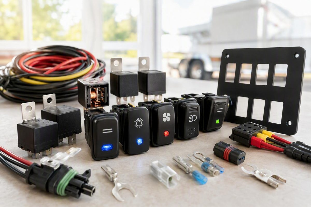
Choose a 12V rocker switch by matching its DC contact rating, circuit topology, operating action, load current, environmental protection, and physical fit. Do not choose by a 12V LED label, advertised amperage, or pin count alone. If an accessory has substantial startup or stall current, use the rocker to control a properly selected relay or contactor rather than carrying the accessory current through the switch.
The short answer: match six specifications before buying
Work through these checks in order:
- Explicit 12VDC contact rating: Confirm that the contacts—not merely the internal lamp—are rated at the intended DC voltage.
- Circuit topology: Choose SPST, SPDT, DPST, or DPDT according to what the circuit must connect or redirect.
- Operating action: Decide whether each active position should remain selected or return when released.
- Normal and peak current: Obtain the load’s running current and its startup, inrush, or stall current where applicable.
- Environmental sealing: Establish which side of the panel needs protection and whether the rating requires a gasket, connector, enclosure, or particular installation method.
- Panel and terminal fit: Check the cutout, supported panel thickness, body depth, retention clips, terminals, connector, and wire clearance.
Three specifications are commonly confused:
- Contact voltage is the voltage the switching mechanism is designed to interrupt.
- Contact current is the current the contacts may carry and switch under stated conditions.
- Illumination voltage is the operating voltage of the internal LED or lamp.
A rocker advertised as having a “12V LED” may have contacts with a different rating—or no published DC contact rating at all. An AC-only contact rating also does not establish safe DC capacity. DC switching presents different arc behavior because the current does not pass through the regular zero crossings found in AC, so the intended DC rating must be stated rather than inferred.
Use the required circuit behavior to narrow the switch type before comparing legends, lamp colors, or bezel styles:
| Application | Likely topology | Action | Architecture |
|---|---|---|---|
| Basic light or moderate resistive load | SPST | Maintained ON-OFF | Direct only if the exact DC rating covers the load |
| Horn or press-only command | SPST | Momentary (ON)-OFF |
Direct or relay-controlled as specifications require |
| Select between two modes | SPDT | ON-ON or ON-OFF-ON | Routes one input to either output |
| Switch two isolated circuits together | DPST | Usually maintained | Both paths operate together |
| Reversible motor or actuator | DPDT center-off | Often momentary | Polarity reversal or relay control |
| High-inrush accessory | Depends on command | Maintained or momentary | Rocker controls a relay or contactor |
These labels describe electrical functions, not universal terminal layouts. Ratings, terminal arrangements, illumination circuits, sealing, and available functions can differ within one product family. Carling’s catalog, for example, lists multiple rocker series with different pole counts, terminations, cutouts, DC ratings, and configuration-dependent sealing. Verify the complete part number against its current datasheet before ordering or energizing the circuit.
Choose the circuit and action that match the job
A rocker switch uses a pivoting actuator to open, close, or redirect one or more circuit paths. Pole describes how many electrically separate paths the switch controls. Throw describes how many connection choices each pole has.
SPST — single pole, single throw: One circuit path is either open or closed. This is the usual arrangement for basic on/off accessory control.
SPDT — single pole, double throw: One common input connects to either of two outputs. An ON-ON version always selects one output or the other. An ON-OFF-ON version adds a center position in which neither output is selected. It can select between two modes, but it does not independently switch two circuits.
DPST — double pole, single throw: Two electrically isolated paths open or close together. Each pole still needs to be suitable for its assigned voltage, current, and load.
DPDT — double pole, double throw: Two switched paths each select between two connections. When correctly cross-wired, a DPDT switch can reverse the polarity delivered to a DC motor or linear actuator and therefore reverse its direction.
Follow the exact switch and equipment diagrams for polarity-reversing wiring. An incorrect terminal assignment or cross-jumper can connect positive directly to negative. Before adding jumpers, isolate every power source and map the switch contacts in each position. Vendor guidance for actuator controls confirms the DPDT polarity-reversal arrangement while also stressing that the switch and associated circuit must suit the load. Firgelli’s actuator guide explains this DPDT control method.
The second choice is maintained versus momentary:
- A maintained rocker stays in its selected position after release.
- A momentary rocker springs back when released.
- Parentheses identify momentary positions.
(ON)-OFFhas one spring-return ON position;(ON)-OFF-(ON)has momentary operation in both directions around a stable center OFF position.
For an ordinary accessory that should remain on, a maintained SPST ON-OFF switch is the straightforward choice. For a horn, starter command, washer pump, or another press-only input, use a momentary SPST (ON)-OFF action if that matches the controlled system.
For a reversible actuator that should stop when the operator lets go, a momentary DPDT center-off switch provides hold-to-move control. A maintained DPDT ON-OFF-ON switch leaves the selected direction active, so use it only where the complete motion system safely handles continued operation, stopping, and travel limits.
One switch can command multiple actuators wired in parallel if the control and power devices are designed for the combined load. That arrangement does not guarantee synchronized movement. Differences in loading, voltage drop, wear, age, and manufacturing tolerances can cause the actuators to drift apart. Applications requiring alignment need suitable feedback and synchronized control.
Read the DC rating in the context of the load
Start with a published contact rating at the intended DC voltage. Do not translate a rating such as 10A at 125VAC into an assumed 12VDC capacity. The voltage type matters, and the printed amperage is not a universal allowance independent of test conditions.
A switch’s usable capacity can depend on:
- Load type: resistive, inductive, capacitive, or lamp-based
- Pole and circuit arrangement
- Terminal and connector option
- Duty cycle and switching frequency
- Ambient temperature and heat buildup
- Normal current and startup or stall current
- Exact ordering code
A moderate resistive load within the exact switch specification may be suitable for direct switching. Motors, pumps, compressors, winches, actuators, and solenoids need more scrutiny. Their startup or stall current can exceed normal running current, while opening an inductive circuit imposes additional switching stress.
There is no reliable universal amperage margin or relay threshold for every 12V circuit. Obtain the accessory manufacturer’s normal and startup or stall current, then compare both with the rocker manufacturer’s DC specifications for that load type and configuration. If the documentation does not establish suitability, do not treat a faceplate’s advertised amperage as permission to switch the load directly.
Direct switching versus relay control
In a direct-load circuit, accessory current passes through the rocker. This keeps the component count low, but it also subjects the switch contacts, terminals, and panel wiring to the full load.
In a relay-controlled circuit, the rocker operates only the relay coil or electronic control input. The relay or contactor contacts carry the accessory current. This can reduce current through a dashboard or control panel and allow the high-current switching device to be positioned closer to the load.
A conceptual relay architecture is:
- A supply protected by an appropriately selected source-side fuse or circuit breaker feeds the relay’s load-contact circuit.
- Appropriately rated relay contacts feed the accessory.
- The rocker switches the relay coil or control input.
- The control and load circuits return through their intended paths.
This architecture does not determine the required fuse, conductor, relay, or suppression ratings. Those choices depend on the accessory specifications, available fault current, wire length, voltage drop, insulation, routing, ambient temperature, connector capacity, and duty cycle. High-current selection guidance treats load type, inrush, duty cycle, temperature, overcurrent protection, conductors, terminals, voltage drop, and suppression as one system rather than relying on switch amperage alone. Taclex summarizes these interacting load-selection factors.
Datasheet figures are useful only when tied to the exact configuration. Selected Carling V-Series configurations are listed at up to 20A at 12VDC. Selected L-Series rating codes list 15A or 20A at 12V. Neither figure applies to every circuit, termination, load, or part number, and neither means that any nominally 20A rocker can directly control a motor drawing 20A in normal operation. The L-Series datasheet shows how ratings depend on the selected code and circuit.
The rest of the circuit matters as much as the rocker. Use application-appropriate overcurrent protection, conductors, terminals, crimps, connectors, strain relief, corrosion protection, and load-specific suppression. A correctly rated switch attached to a loose quick-connect terminal or poor crimp can still create a resistive, unreliable connection.
Check panel fit, terminals, and sealing as a system
Measure the installation before choosing the legend, lamp color, or bezel style. Record:
- Panel cutout width and height
- Acceptable panel-thickness range
- Switch-body depth behind the panel
- Actuator and bezel dimensions
- Clearance for snap-in retention clips
- Terminal size and orientation
- Rear connector or individual terminal depth
- Wire-bend radius and service-loop clearance
- Nearby obstructions, braces, ducts, and switches
Face dimensions alone are not enough. A replacement can cover the opening yet fail to seat because its body is too deep, its retention clips do not engage the panel, or its terminals point into an obstruction.
Common quick-connect tabs include 0.187-inch and 0.250-inch formats. Matching the tab width establishes only one mechanical dimension. It does not confirm the circuit function, contact rating, pinout, lamp wiring, temperature range, or sealing.
Dimensions vary among switches that look similar. The Carling V-Series catalog lists a 0.830 × 1.450-inch cutout and several termination options. Its sealing specifications also vary by series and configuration, with some claims dependent on the specified connector. Carling’s catalog documents these V-Series dimensions and configuration differences.
Carling’s L-Series documentation specifies a 44.0 × 22.0 mm opening, a supported panel-thickness range of 0.76–3.96 mm, and options for 0.187- or 0.250-inch quick-connect tabs. It lists IP67 protection for above-panel components of the actual switch, not blanket protection for the rear wiring or every completed installation. The L-Series datasheet ties these dimensions and sealing conditions to its ordering system.
Treat sealing as an installed-system property
Words such as “waterproof,” “marine,” and “sealed” are not substitutes for model-specific test conditions. Check:
- The stated IP level
- The exact switch part number and configuration
- Whether protection applies above the panel, below it, or both
- Whether a gasket, mounting frame, or panel finish is required
- Whether the rating depends on a specified rear connector
- The documented test conditions and orientation
- Protection for terminals, splices, connectors, and wire entries
Above-panel sealing protects the exposed actuator area only under the documented conditions. It does not automatically protect bare rear terminals. For an exposed boat, open cab, trailer, or off-road panel, consider connector seals, terminal protection, enclosure drainage, wire support, corrosion control, and panel sealing as parts of the same installation.
Ingress and lifecycle figures supplied by a manufacturer describe tested or claimed product configurations. They are not independent proof of how every finished installation will perform.
Wire illuminated switches by topology, not pin count
Before wiring, moving terminals, or using a meter in resistance or continuity mode, isolate every power source. That can include the starting battery, auxiliary battery, charger, shore-power converter, solar supply, or another backfeed path. Disconnect the switch from circuit wiring where necessary and confirm that no voltage is present before selecting resistance or continuity mode. Keep any later live voltage-under-load diagnosis separate from continuity testing. Manufacturer wiring guidance likewise begins with disconnecting the negative battery terminal or otherwise isolating the source. DAIER’s wiring guide documents this initial isolation step.
Common three-terminal SPST example
One common illuminated SPST topology uses:
- Fused positive connected to the switch supply terminal
- Switched output connected to the accessory or relay trigger
- Ground connected to the internal lamp
This is an example, not a universal three-pin pinout. In this arrangement, the contact path connects supply to output when the rocker is on, while the third terminal completes the illumination circuit. The accessory may therefore operate without the lamp ground connected, but the indicator remains dark. Wiring Depot illustrates this supply-output-ground arrangement.
Another three-terminal model may use independent illumination, switch the ground side, or arrange the lamp differently. Read the case markings and exact diagram before making connections.
One five-pin dual-illumination example
One documented five-pin topology assigns:
- Pin 2: fused 12V positive input
- Pin 3: switched output to the accessory or relay trigger
- Pin 7: common LED ground
- Pin 6: optional dashboard-light input for the lower backlight
- Pin 8: no external connection in that particular internal design
These assignments are model-specific, not a standard shared by every five-pin rocker. In the documented relay version, Pin 3 operates the relay control side instead of supplying the accessory directly. DAIER’s five-pin guide shows this particular internal arrangement and relay-trigger connection.
Dual-illumination switches can support several behaviors:
- Active indicator: Illuminates when the switched output is active.
- Dash-linked backlight: Follows the instrument-light circuit.
- Always-on locator: Receives constant positive so the switch remains visible in the dark.
An always-on locator creates continuous battery draw. Whether that draw is acceptable depends on the switch, battery, storage duration, and other parasitic loads.
If no reliable diagram is available, remove the switch from the circuit as needed, isolate every supply, verify the absence of voltage, and then map continuity with a multimeter. Record which terminal pairs connect in OFF, ON, and any momentary positions. Do not use trial-and-error energization to identify unknown terminals; an incorrect connection can create a short or damage an internal LED. If the switch cannot be isolated and identified confidently, obtain the correct documentation or qualified help.
Exact wire gauge, fuse size, relay rating, and suppression components cannot be selected from the switch pin count. They require the accessory’s electrical specifications and the circuit’s length, routing, environment, duty cycle, and fault conditions.
Use a full compatibility checklist when replacing a switch
No—another switch is not interchangeable merely because it has the same number of pins. Two five-pin rockers can assign supply, output, ground, backlight, and indicator functions differently. They can also contain different contact circuits despite having terminals in similar physical positions.
Match all of the following:
- DC contact voltage and current rating
- Supported load type
- Pole and throw
- Number of positions
- Maintained or momentary action at each position
- Terminal continuity map
- Internal illumination topology
- Lamp or LED voltage
- Panel cutout
- Supported panel thickness
- Rear body and connector depth
- Terminal size and orientation
- Connector keying and cavity arrangement
- Required sealing conditions and accessories
- Operating-temperature range
- Applicable lifecycle and duty limitations
Do not stop after matching the face. Body depth, retention clips, terminal direction, connector shell, and wire-bend clearance can prevent a physically similar switch from fitting.
Keep the lamp specification separate from the contact specification. One miniature rocker listing identifies a 12V amber LED but provides contact ratings only at 125VAC and 250VAC. The listing therefore does not establish 12VDC contact capacity. The product page shows the separate LED and AC contact specifications.
Before removing the old switch, record its complete part number and photograph the connector and wire positions from more than one angle. Label the wires if necessary, but do not assume color establishes function. Verify the circuit against its documentation or by continuity testing on a fully isolated and electrically disconnected switch.
Troubleshoot by symptom before replacing parts
Disconnect power before moving terminals, measuring continuity, repairing crimps, or investigating heat. A replacement switch will not correct a crossed connection, poor crimp, damaged load, unsuitable conductor, or incorrect circuit architecture.
| Symptom | Checks to make first |
|---|---|
| Accessory works, but LED is dark | Check lamp ground, illumination supply, LED polarity, and the model’s internal illumination topology. |
| Backlight stays on | Determine whether the backlight terminal is connected to constant positive rather than the intended switched dash-light circuit. |
| Fuse or breaker opens immediately | Keep power isolated; inspect for a short, incorrect terminal assignment, damaged insulation, excessive inrush, a failed load, relay faults, or DPDT cross-wiring that joins positive to negative. |
| Motor or actuator runs in only one direction | Check DPDT continuity in both positions, cross-jumper placement, output connections, and the motor or actuator. |
| Switch or connector becomes hot | Disconnect power; inspect for overload, excessive inrush, loose terminals, poor crimps, corrosion, undersized conductors, or excessive voltage drop. |
| Operation is intermittent | Check terminal retention, crimp quality, strain relief, connector condition, control voltage, and voltage at the load while operating. |
A dark LED does not necessarily mean the contacts have failed. If the load operates normally, the problem may be confined to the lamp ground, backlight feed, LED polarity, or internal illumination circuit.
An immediately opened fuse or breaker has several possible causes; it does not prove one specific fault. Keep the circuit de-energized until the terminal map, wiring, load condition, and overcurrent-protection arrangement have been checked.
Heat requires prompt isolation rather than continued operation. Heating can originate at the contacts, quick-connect tabs, crimp barrel, connector cavity, or conductor. Discoloration, softened plastic, corrosion, or reduced terminal grip means the affected connection—and the reason it failed—must be addressed. Manufacturer troubleshooting guidance similarly directs users to disconnect power if a rocker housing becomes hot. DAIER’s troubleshooting guide covers dark illumination, shorts, overcurrent, and switch heating.
If load current, startup or stall current, pinout, overcurrent protection, or the cause of heating cannot be established safely, have the circuit evaluated by a qualified technician.
Before final energization, confirm the exact rocker’s 12VDC contact rating, topology, action, pinout, illumination voltage, sealing conditions, cutout, panel-thickness range, terminal format, operating-temperature range, and lifecycle conditions. If the accessory has substantial inrush or stall current, let a properly selected relay or contactor carry the load. Isolate every power source, provide application-appropriate source-side overcurrent protection, and map unknown terminals only on a de-energized, electrically disconnected switch.