
24 min read ·
Choose the Right Low-Voltage Dimmer Before You Cut a Wire
Compatibility requires matching the lighting architecture, dimming method, connected load, conductors, mounting format and operating environment.
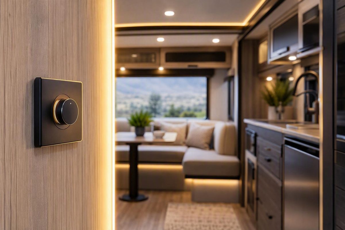
A 12V dimmer switch is not selected by voltage alone. It must match the lighting architecture, dimming method, connected load, available conductors, mounting format, and operating environment.
That description does not fit every system. Constant-current LED modules, RGB or RGBW strips, household installations supplied by 120V AC, and electronic dimmers requiring extra conductors need different controls or wiring arrangements.
The practical rule is simple: identify the complete circuit first, then choose the control.
Start with the circuit, not the switch
Before comparing knobs, touch panels, or wattage claims, classify the lighting system.
-
Is the lighting supplied directly by nominal 12V DC? - If yes, determine whether the fixtures are constant-voltage and explicitly dimmable. A compatible standalone 12V DC PWM dimmer may fit. - If no, continue through the other categories.
-
Is the LED assembly a constant-current module? - If yes, use a compatible constant-current driver or a controller designed for that module. - Do not assume an ordinary constant-voltage 12V dimmer can control it.
-
Is it an RGB, RGBW, or tunable-white system? - Use a controller that manages the required channels and brightness. - Do not casually stack a single-channel dimmer with a color controller.
-
Does the installation begin with 120V AC household power? - If a separate 12V power supply is already present, a suitable low-voltage dimmer may be installed on its DC output. - If dimming will occur on the AC side, the wall dimmer and LED driver must be designed to work together. - An integrated dimmer-driver is another option: it accepts AC input and produces a controlled low-voltage DC output.
For an ordinary low-voltage arrangement, the conceptual circuit order is:
12V DC source or power supply
        |
        v
Circuit protection
        |
        v
Compatible 12V DC dimmer
        |
        v
Dimmable 12V lighting load
The standalone dimmer operates on the DC side. It does not replace the 120V-to-12V power supply. Manufacturer guidance similarly distinguishes low-voltage DC dimmers installed between a power supply and the LEDs from 120V wall dimmers used with compatible dimmable drivers. It also directs RGB installations toward an RGB controller rather than an additional dimming method in the same circuit (Armacost’s low-voltage LED dimming guide).
An integrated dimmer-driver is a different category. Instead of receiving 12V DC, it receives 120V AC, converts that input to regulated 12V DC, and controls the output. This may simplify some indoor installations by combining two functions in one device, but it is still line-voltage equipment and must be installed according to its current instructions and the requirements applicable to the location.
A conventional household wall dimmer does not become a 12V DC dimmer merely because the lights ultimately operate at 12V. It remains an AC-side control and must be paired with a driver compatible with that dimming method. Likewise, a DC-only switch must never be connected to 120V AC.
Qualification checklist
Before shopping, record:
- Actual system voltage and expected operating range
- AC-fed or DC-fed architecture
- Constant-voltage or constant-current load
- Confirmation that the lights are dimmable
- Existing power-supply or LED-driver model
- Single-color, tunable-white, RGB, or RGBW lighting
- Total connected load in watts and amps
- Number and function of conductors at the proposed control location
- Indoor, mobile, damp, outdoor, marine, or other operating setting
If any of the first five items remains unknown, product comparison is premature. A large wattage rating cannot cure the wrong control method.
How PWM changes LED brightness—and what it does not guarantee
PWM controls apparent brightness by switching the output on and off rapidly. The proportion of each switching cycle spent on is the duty cycle.
At a high duty cycle, the LEDs are on for most of each cycle and appear bright. At a low duty cycle, they are on for less of each cycle and appear dim. During an on-pulse, the LED product receives its normal operating level rather than a continuously reduced level. The eye integrates the pulses into an apparent average brightness.
A simplified illustration looks like this:
High brightness:
ON  ████████  OFF ██  ON ████████  OFF ██

Medium brightness:
ON  █████  OFF █████  ON █████  OFF █████

Low brightness:
ON  ██  OFF ████████  ON ██  OFF ████████
Changing duty cycle is not the same as changing switching frequency. Duty cycle describes how much of a cycle is on; frequency describes how many cycles occur per second.
PWM is common in constant-voltage LED controls, but it does not make every 12V LED dimmable. A fixture may contain resistors, a regulated driver, or other internal electronics. Those components determine how it responds to a switched supply. A “12V” label identifies nominal operating voltage, not the accepted dimming method.
This is why reports about old automotive rheostats vary. A simple replacement lamp containing LEDs and a resistor may respond when current is reduced. A regulated instrument or lamp may hold its output steady, shut down, flicker, or require a dedicated control input. Successful use with one dashboard lamp does not prove that a rheostat will work with every LED replacement.
PWM versus resistance-based dimming
A rheostat or series resistance reduces current by introducing resistance into the circuit. It can be simple, but its behavior depends on the load, and the resistive element dissipates power as heat. PWM instead uses electronic switching to control on-time and can provide a broad, repeatable adjustment range.
That does not make PWM universally superior or lossless. The LEDs still need appropriate current limiting, whether it comes from internal fixture electronics, a resistor, or a regulated driver. The dimmer’s switching components also have losses.
PWM combined with a series resistor is not automatically more efficient than continuous resistor dimming at the same average current. In one forum calculation, averaging the resistor’s full on-state dissipation over a 50% duty cycle produced the same calculated resistor loss as a larger resistor carrying an equivalent continuous current. That conclusion is limited to the assumptions in the worked comparison: improved efficiency requires suitable power-conversion design, not merely the presence of a PWM signal (All About Circuits discussion of PWM and resistor losses).
Flicker, cameras, and interference
A PWM light can look steady to a person yet produce bands or pulsing on a camera. Results depend on PWM frequency, duty cycle, camera shutter behavior, modulation depth, and the fixture. Low brightness may reveal behavior that is not apparent near full output.
Higher switching frequencies may reduce visible flicker or camera artifacts, but no single frequency guarantees acceptable results in every application. Long output wiring and LED strips can also make high-frequency switching more challenging from an electromagnetic-interference perspective. A dimmer developer’s technical overview discusses both the possible camera benefit of higher frequencies and the possibility of increased EMI on long wiring, while presenting its frequency recommendations as application preferences rather than universal rules (QuinLED’s explanation of PWM dimming).
Treat “flicker-free,” “silent,” and similar seller language as claims to verify with the intended fixtures. Useful questions include:
- What is the PWM frequency?
- Is it fixed or adjustable?
- What is the lowest stable brightness with this fixture?
- Does the light shut off cleanly at minimum?
- Is flicker visible in peripheral vision?
- Does a phone or video camera show banding?
- Does the dimmer or fixture make audible noise?
- Does operation affect nearby radios or electronics?
- How long is the dimmer-to-load wiring?
When camera performance or radio compatibility matters, test the actual combination rather than relying on the “PWM” label alone.
Calculate the load in both watts and amps
A dimmer has to pass two selection tests:
- The total load must remain below its wattage limit.
- The total current must remain below its amperage limit.
Passing only one is not enough.
Start with a fixture schedule:
| Fixture or strip section | Quantity or length | Unit rating | Total watts |
|---|---|---|---|
| Fixture A | Quantity | Watts each | Quantity × watts |
| Fixture B | Quantity | Watts each | Quantity × watts |
| Strip section | Installed length | Watts per unit length | Length × rating |
| Circuit total | Add all totals |
Then estimate current:
Current (amps) = Power (watts) ÷ Operating voltage (volts)
Use the actual or relevant design voltage where available, and check the manufacturer’s current specification directly. The arithmetic is a screening tool, not a substitute for the datasheet.
Example 1: four small fixtures
Four lights rated at 3W each produce:
4 × 3W = 12W total
12W ÷ 12V = approximately 1A
The prospective dimmer must support more than 12W and more than 1A. The planned load should also remain below each published maximum rather than being designed to sit at the limit.
Example 2: 60W of LED strip
For 60W of nominal 12V strip lighting:
60W ÷ 12V = approximately 5A
A dimmer advertised as “100W” is not automatically suitable. Its separate current rating must also exceed 5A with appropriate capacity remaining. If its current limit were only 4A, it would fail the selection test even though 60W is below the advertised 100W ceiling.
When watt and current ratings do not align
RecPro lists its touch RV control at 12V DC with maximum LED-load figures of 50W and 4A. Yet:
4A × 12V = 48W
At exactly 12V, the current rating therefore imposes a 48W effective ceiling before any additional capacity is retained. The lower applicable constraint should govern rather than the larger number in the listing (RecPro’s RV touch-dimmer specifications).
The available evidence does not support one universal derating percentage.
Where a manufacturer gives a product-specific recommendation, follow it. For example, HitLights recommends operating its 40W integrated dimmer-driver at about 80% of rating for longevity. That advice belongs to that product and should not be turned into a universal rule for unrelated DC dimmers (HitLights’ integrated dimmer-driver specifications).
Do not overlook uncertainty in strip-light estimates. If a strip is rated by length, calculate from the actual installed length. If its manufacturer states both maximum length and maximum power, satisfy both. Include every fixture connected to the channel, even if the lights are distributed across several branches.
Wire and circuit protection are separate design questions
A dimmer’s amp rating does not, by itself, establish conductor size or circuit-protection values.
The supplied product evidence does not provide authoritative, generally applicable fuse-placement, fuse-size, cable-size, enclosure, or strain-relief instructions. Do not infer those requirements from this article or from a dimmer’s headline rating. Use the current equipment instructions and authoritative guidance applicable to the vehicle, vessel, building, or other installation.
Understand two-, three-, and four-wire dimmer layouts
Count conductors by function, not color. Wire colors vary among vehicles, builders, product manufacturers, and previous repairs.
The four functions relevant to a general DC lighting control are:
- Source positive
- Source negative
- Load positive
- Load negative
Not every dimmer uses four separate leads. Its internal topology determines which conductors it needs and which side of the load it switches.
Basic conceptual order
SOURCE SIDE                            LOAD SIDE

Fused +12V  ───────>  DIMMER  ───────>  Light positive
Source 0V   ───────>  as required ───>  Light negative
The phrase “as required” matters. A high-side control typically switches the positive side. A low-side control switches the negative return. A four-wire control may have separate positive and negative input and output connections. Some three-wire electronic controls need a constant supply and return plus one controlled lead.
Always use the selected product’s current diagram.
Why a two-wire switch is different
A simple mechanical on/off switch often interrupts only one conductor:
Fused source positive ──> ON/OFF SWITCH ──> Light positive
Source negative ──────────────────────────> Light negative
Only two switch terminals are required because the switch itself does not need continuous power. It simply opens or closes the conductor.
A powered touch, memory, or electronic dimmer may need constant positive and negative connections to operate its electronics, plus a controlled output. A four-wire unit may use this arrangement:
Source positive ──> Dimmer input positive
Source negative ──> Dimmer input negative

Dimmer output positive ──> Load positive
Dimmer output negative ──> Load negative
The documented RecPro touch control is an example: its seller identifies four wires comprising positive and negative inputs and positive and negative outputs. That arrangement is fundamentally different from a two-terminal mechanical switch.
An existing two-wire switch location may therefore lack the constant negative or another conductor required by the replacement. Finding “two wires in the wall” does not prove that a three-wire dimmer can use one as ground, nor does the presence of a nearby conductor establish its function.
Three-wire controls
Three-wire configurations vary. Possible arrangements include:
- Constant positive, negative, and switched positive output
- Positive input, negative input, and switched negative output
- Supply positive, load positive, and a common negative reference
- Product-specific control or sense leads
A three-wire product described as high-side must not be wired from a generic low-side diagram. Conversely, a low-side dimmer cannot be assumed to replace a positive-side switch without changing the circuit according to the product documentation.
Identify source and load conductors carefully
Physical tracing and continuity checks are conceptually different from energized voltage measurements.
- Physical tracing and continuity testing are performed with the circuit isolated and verified de-energized.
- An energized measurement, if needed, calls for an appropriate meter, protected probes, and competent procedures suited to the system.
- This article does not provide a step-by-step live-testing procedure.
The objective is to distinguish the conductor connected to the source, the conductor continuing to the lighting load, the negative return, any pass-through conductor serving another load, and any separate control lead.
An RV owner-forum installation illustrates why verification matters: participants advised using a test light or meter to distinguish source-side and load-side conductors before connecting one particular high-side dimmer. The reported result applied only to that RV and product, not to all dimmers or wire colors (Alliance RV Owners discussion of a high-side retrofit).
Community diagrams can also reveal retrofit constraints without serving as universal instructions. In one RV discussion, a proposed three-wire dimmer location did not have the constant power conductor the control required. The contributor concluded that another conductor would be needed at that location; the wire colors and lead functions were specific to the named product (community analysis of a three-wire RV dimmer circuit).
If a sales listing and installation manual disagree about conductor count, switched side, or terminal function, stop. Obtain the current manufacturer diagram for the exact model and revision before connecting power.
Connect multiple 12V lights as a compatible load
One dimmer can control several fixtures if all of them:
- Operate from the same nominal voltage
- Are compatible with the dimming method
- Belong on the same control zone
- Stay within the dimmer’s amp and watt limits when combined
- Are connected according to the dimmer and fixture instructions
For nominally 12V fixtures, the usual external arrangement is parallel wiring:
Dimmer-controlled positive
        |
        +----------> Light 1 positive
        |
        +----------> Light 2 positive
        |
        +----------> Light 3 positive
        |
        +----------> Light 4 positive

Appropriate negative connection
        |
        +----------> Light 1 negative
        |
        +----------> Light 2 negative
        |
        +----------> Light 3 negative
        |
        +----------> Light 4 negative
Parallel wiring allows each nominally 12V fixture to receive the intended supply voltage. The exact negative connection depends on the dimmer:
- With a high-side dimmer, fixture negatives may return to the common source negative.
- With a low-side dimmer, the controlled side may be the negative return.
- With a four-wire input/output control, the load conductors connect to the designated output leads.
Do not redraw the negative side from habit. Follow the selected topology.
Why series wiring is usually the wrong default
A series chain routes current through one fixture and then the next. Their internal electronics may respond differently as conditions change.
A series arrangement may also cause uneven brightness. Depending on the fixture design and failure mode, an open connection can interrupt the shared current path. Campervan lighting guidance consequently presents parallel wiring as the general preference for complete 12V puck-light fixtures (The Van Conversion’s series-versus-parallel lighting guide).
Do not confuse the internal series-parallel arrangement of LED elements inside a manufactured strip or fixture with the external wiring of complete 12V products. A manufacturer may use series groups internally while still providing a 12V positive and negative input intended for parallel branch wiring.
Plan zones deliberately
Separate zones need separate controlled channels. For example:
- Front ceiling lights: Dimmer A
- Rear ceiling lights: Dimmer B
- Reading lights: Local switches or another dimmer
- RGB accent strip: RGB controller
- Exterior lights: A control rated and documented for that application
Do not combine zones merely because one large dimmer has sufficient capacity. Separate control may improve usability and avoid mixing incompatible fixture types. Any claimed benefit involving cable routing or current distribution must be evaluated as part of the actual circuit design rather than assumed.
When several lights share one channel, calculate the full connected load—not merely the number normally turned on. If every fixture is electrically attached to the same output, size the control for the possibility that all will operate together.
Match the control style to the installation
After confirming electrical compatibility, choose the interface and form factor.
| Control style | Practical advantages | Questions to ask |
|---|---|---|
| Rotary | Familiar tactile adjustment; easy to change without looking | Does the knob push for on/off? How deep is the body? |
| Slider | Visible indication of the approximate setting | Is on/off integrated or separate? Will the mechanism fit the available box? |
| Toggle plus dimmer | Clear on/off action separate from level control | Is the toggle switching DC or controlling internal electronics? |
| Touch | Compact appearance; suitable for some RV panels | Does it need constant power and negative? What is its standby draw? |
| RF remote | Can avoid adding a physical control-wire route | Does the receiver remain locally operable? What happens if the remote is lost? |
| Wi-Fi control | App or automation options | Does it require an account, hub, network, or cloud service? |
| Multi-channel controller | Suitable for zones, RGB, or tunable-white loads | Are channel voltage, current, and load types compatible? |
A rotary control is often convenient when tactile adjustment matters. Some combine dimming with a push-on/push-off knob. A slider gives a visible indication of level and may include a separate switch. A touch panel can fit a compact RV interior, although its electronics may require more conductors than the switch it replaces.
The interface does not reveal the electrical topology. Two products that look similar from the front can use entirely different wiring behind the panel.
RF and Wi-Fi controls can help when running a new control cable would be difficult. The receiver still needs suitable source and load connections, and every component must belong to a compatible system. A wireless command link does not remove the need for correct branch-circuit design or load calculations.
Measure the installation space
Check:
- Panel or wall cutout
- Faceplate dimensions
- Body depth
- Clearance available behind the control
- Wall-box compatibility, where applicable
- Surface-mount versus recessed construction
- Available conductor length
- Access to terminals or connectors after installation
- Normal operating position and accessibility
Do not assume that “in-wall,” “panel mount,” or “compact” establishes every physical requirement. Check the current product instructions for mounting, connection protection, cable support, and any required box or enclosure. The available evidence does not support one universal enclosure or strain-relief specification for every installation type.
Battery-system details
Memory behavior can matter. Some users want the light to return to its previous level after a tap; others want a predictable brightness when upstream power is restored.
Electronic dimmers can also consume standby current while “off.” That may be insignificant in a regularly charged system yet relevant in a vehicle stored for long periods. The available evidence does not provide a reliable measured comparison among the example products, so request a standby-current specification if it affects the design.
No interface is universally best. Choose around accessibility, available space, conductor access, lighting zones, expected use, and the consequences of a failed remote or network connection.
Four documented product types and where each fits
These products illustrate four different approaches. They are not direct substitutes because they serve different circuit architectures, wiring layouts, and installation formats.
| Device type | Supported voltage | Stated 12V capacity | Control style | Wiring information | Installation format | Environment restrictions | Unresolved conflicts |
|---|---|---|---|---|---|---|---|
| SunBright rotary low-side PWM dimmer | 12V or 24V DC | 15A or 180W maximum at 12V | Push on/off rotary knob | Seller identifies low-side PWM, but alternates between three and four wires | Panel-mounted with decorative faceplate | Specific environmental suitability is not established by the supplied listing | Three versus four wires; 24V rating stated as both 7A and 7.5A (SunBright product page) |
| aspectLED in-wall PWM control | 12V or 24V DC | 100W maximum | Dimming control with on/off toggle | Seller says it installs between the DC supply and LEDs; a field labeled “Input Signal” says “2 Wires,” but complete terminal functions are not established here | Standard single-gang switch box | Suitability for a particular setting must be confirmed from current documentation | Dimming range appears as both 0–100% and 10–100% (aspectLED product page) |
| RecPro RV touch control | 12V DC | 4A or 50W listed | Tap on/off; hold to dim or brighten | Four wires: positive and negative input and output | Compact RV-oriented panel control | No weather-resistance claim is established | Two-location switching is not established; 4A equals 48W at exactly 12V (RecPro product page) |
| HitLights integrated dimmer-driver | 120V AC input; regulated 12V DC output | 40W or 3.3A | Slider with on/off control | Requires AC line, load, and neutral; provides 12V DC output | Standard recessed single-gang box | IP30 and dry indoor use only | Lower dimming limit appears as both 5% and 10% (HitLights product page) |
The table reports seller or manufacturer-page specifications, not independent testing. Where documentation conflicts or terminal functions remain unclear, treat the field as unresolved until the current manual for the exact model confirms it.
SunBright rotary low-side PWM dimmer
SunBright lists a 12V/24V DC low-side PWM control with a push-on/push-off rotary knob. At 12V, the seller states a maximum of 15A or 180W. The page also supplies cutout and faceplate dimensions, which may help assess a panel installation.
The concern is documentation consistency. One section says four wires while another says three. The page also alternates between 7A and 7.5A for the 24V rating. Because conductor count and current rating affect both installation and load selection, the current specification sheet and installation guide should settle those points before purchase (SunBright’s rotary-dimmer listing).
Claims about quiet or flicker-free operation are seller claims rather than independent test results. Verify those characteristics with the intended lights if they matter.
aspectLED in-wall PWM control
The aspectLED control is listed for 12V or 24V DC dimmable lighting, with a 100W maximum, a standard single-gang format, and an on/off toggle. It belongs on the low-voltage side between a compatible DC power supply and the LED load.
The seller expressly describes compatibility with its own dimmable fixtures, so compatibility with another brand should be confirmed rather than inferred. Its page also gives two different dimming ranges—0–100% in one place and 10–100% elsewhere. The listing’s “Input Signal: 2 Wires” field does not establish the complete terminal layout or prove that the product can replace any existing two-wire switch (aspectLED’s in-wall PWM dimmer listing).
This format may fit an indoor-style low-voltage wall control where a compatible box is available. The supplied listing does not establish suitability for an exposed vehicle panel, damp location, or other demanding environment.
RecPro touch RV control
RecPro’s compact touch unit is oriented toward 12V RV LED lighting. A tap turns the lights on or off, while holding the control changes brightness. It has separate positive and negative leads on both the input and output sides.
Because all four conductor functions are needed, this style is not necessarily a direct replacement for a two-terminal mechanical switch. The connected LEDs must also be confirmed as dimmable. The listing does not establish weather resistance, motor compatibility, or support for control from two locations.
HitLights integrated dimmer-driver
The HitLights device is not a standalone DC dimmer. It accepts household AC input and creates a regulated 12V DC output. It requires a neutral conductor, installs in a recessed single-gang box, and is limited to dry indoor use.
This architecture may fit a location where AC power is present and an all-in-one driver and dimmer is wanted. It is not a drop-in replacement for an RV’s 12V DC switch, and it is not suitable for 24V or constant-current loads. Its published lower dimming limit is internally inconsistent, so that performance point remains unresolved.
Ignore temporary prices, stock claims, review totals, sale deadlines, and shipping promises when comparing these categories. None determines electrical compatibility.
Verify fit, environment, and documentation before purchase
Use a written checklist rather than relying on a product title.
- [ ] Actual input voltage and expected operating range are known.
- [ ] The product accepts that voltage and polarity.
- [ ] The lights are constant-voltage rather than constant-current, unless the controller is specifically designed for constant-current loads.
- [ ] The fixtures are explicitly dimmable by the proposed method.
- [ ] Single-color, RGB, RGBW, and tunable-white requirements are matched.
- [ ] Total watts have been calculated.
- [ ] Total amps have been calculated.
- [ ] Both totals remain below their respective limits with appropriate capacity retained.
- [ ] The available conductors match the required terminal functions.
- [ ] High-side, low-side, or four-wire topology is understood.
- [ ] The current manufacturer wiring diagram is available.
- [ ] Cutout, faceplate, body depth, and rear clearance fit.
- [ ] Mounting, connection protection, and enclosure details have been checked against applicable instructions.
- [ ] The operating environment matches the product’s documented rating.
- [ ] Circuit protection and conductor sizing have been determined separately from authoritative guidance.
- [ ] Any relevant standby draw, memory behavior, or wireless dependency is acceptable.
Environment is part of compatibility
“12V” is not an environmental rating. A control documented only for a dry indoor wall installation has not thereby been shown suitable for:
- Damp compartments
- Exterior panels
- Marine locations
- Engine or fuel-system spaces
- Areas exposed to condensation
- High-temperature enclosures
- Vibration-prone mobile installations
- Locations where ignition-protected equipment may be required
The supplied product pages do not establish general requirements for these settings. Confirm environmental suitability from the current manufacturer documentation and the authoritative rules applicable to the installation.
Look for a stated input-voltage range and explicit approval for the intended setting.
Do not apply an LED-load rating to a motor, fan, or other inductive load. The supplied evidence does not establish motor or fan compatibility for the compared dimmers. Use such a control only when the manufacturer explicitly approves the load under an applicable rating.
Resolve documentation conflicts
Compare three documents where available:
- Sales page
- Datasheet or specification sheet
- Installation manual for the exact model and revision
Pay particular attention to:
- Number of wires or terminals
- Terminal functions
- Input-voltage range
- Maximum continuous current
- Maximum power
- Approved load type
- High-side or low-side switching
- Minimum load
- Minimum dimming level
- Mounting instructions
- Ambient-temperature limits
- Environmental designation
A discrepancy is not a minor editorial issue when it changes how the product is wired or loaded. Ask the manufacturer for clarification and retain the applicable documentation with the installation records.
Some performance questions may remain unanswered even after reading the listing:
- PWM frequency
- Minimum stable brightness
- Behavior when power is restored
- Standby current
- Full-load operating temperature
- Persistent glow while nominally off
- Audible noise
- Camera banding
- Radio-frequency interference
- Response to long output wiring
If any of these characteristics is critical, choose a product with adequate technical documentation or test one representative circuit before committing to the full installation.
Stop rather than improvise when:
- The load may be constant-current rather than constant-voltage.
- The fixtures are not confirmed dimmable.
- Required conductors are missing.
- Source-side and load-side conductors cannot be identified.
- The switched side is unknown.
- Amp or watt capacity is inadequate.
- Environmental suitability is not documented.
- Product specifications remain contradictory.
- An LED-only control would be applied to a motor or fan without explicit approval.
- The work involves 120V wiring and the installer lacks the competence or documentation required for that installation.
The compact selection sequence is:
- Identify the lighting architecture.
- Confirm that the lights and driver accept the proposed dimming method.
- Total the load in watts and amps.
- Inspect and identify the available conductor functions.
- Match high-side, low-side, or four-wire topology.
- Match the mounting format and documented environment rating.
- Verify every terminal against the current manufacturer documentation.
The right 12V dimmer is the one demonstrably compatible with the complete circuit—not merely the model with the largest advertised wattage or the preferred control style.
Frequently asked questions about 12V dimmers
Where does a 12V dimmer switch go in the circuit?
A standalone low-voltage dimmer generally goes on the DC side, after the compatible 12V source and circuit protection but before the lighting load:
12V source → circuit protection → dimmer → parallel lighting load
The exact positive and negative routing depends on whether the dimmer is high-side, low-side, three-wire, or four-wire. An integrated dimmer-driver is different: it accepts AC input and creates the controlled 12V DC output itself.
Can a three- or four-wire dimmer replace a two-wire on/off switch?
Not necessarily. A basic two-wire switch may simply interrupt one conductor. A powered electronic dimmer may also require constant positive and negative connections, plus one or two load connections.
Identify every conductor by function and compare the available wiring with the exact dimmer diagram. If the required negative, constant positive, or separate output conductor is absent, additional wiring or a different dimmer may be necessary.
How many 12V LED lights can one dimmer control?
There is no universal fixture count. Add the wattage of all connected lights, calculate current using watts divided by operating voltage, and compare both totals with the dimmer’s limits.
For example, four 3W lights total 12W and draw approximately 1A at 12V. One compatible dimmer can control them if it exceeds both requirements with appropriate capacity remaining. Complete nominally 12V fixtures are normally connected in parallel so each receives the intended voltage.
Does PWM always use less battery power than a rheostat or resistor?
No. PWM can be an effective control method, but it is not automatically lossless. The fixture still needs current limiting, and the dimmer has switching losses. If PWM is used with a series resistor, that resistor still dissipates power during each on-pulse.
Battery consumption depends on the complete circuit, including duty cycle, LED electronics, current-limiting method, dimmer efficiency, standby draw, and wiring losses. Compare measured input power or credible manufacturer data rather than assuming the PWM label guarantees a particular saving.
Can I use a household 120V wall dimmer with 12V LED lights?
Only through a compatible architecture. A conventional 120V wall dimmer operates on the AC side and requires an LED driver specifically designed to accept that dimming method. It must not be connected directly to a 12V DC lighting circuit.
For an existing 12V DC system, use a compatible low-voltage DC dimmer on the output side of the power source. Alternatively, an integrated AC-input dimmer-driver can convert 120V AC to controlled 12V DC when its load, wiring, mounting, and location requirements are satisfied.