
20 min read ·
How to Wire, Protect, and Test a Self-Exciting Alternator
The B+ cable may connect to battery positive or to an electrically equivalent battery-side starter-solenoid or starter junction.
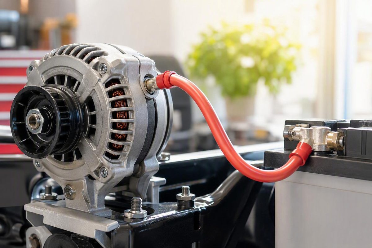
A true one-wire alternator makes the visible wiring simple: one heavy output cable connects the alternator to the battery-positive circuit. The complete charging circuit still includes overcurrent protection, the alternator’s case ground, the engine and battery ground cables, and the vehicle’s main power-distribution system.
This 1 wire alternator wiring diagram and installation guide applies to conventional 12-volt, negative-ground vehicles. Instructions for the exact alternator and vehicle always take precedence.
Confirm That the Alternator Is Really a One-Wire Model
A true one-wire alternator is an internally regulated, self-exciting unit. In normal operation, it needs one external electrical connection: the heavy B+ output cable. It does not ordinarily require an external regulator, ignition-switched exciter wire, or remote-sense wire.
“One-wire” does not mean “no negative connection.” The alternator housing forms the negative side of the charging circuit. Current returns through the case, mounting hardware, bracket, engine block, engine ground cable, and battery-negative cable—or through a dedicated ground cable when one is installed.
Do not assume every internally regulated alternator is a one-wire model. Depending on its design, an alternator may also use:
- A D+ warning-lamp or excitation terminal
- A switched field or excitation connection
- A remote-sense terminal
- A two-wire regulator plug
- A multi-terminal electronic-control plug
- An ECU or charging-system control connection
GM SI-family alternators, for example, have been produced in both one-wire and three-wire configurations. The housing style alone does not establish how the regulator is excited or where it senses voltage, as explained in this comparison of one-wire and three-wire alternators.
Before connecting anything:
- Record the part number. Look for a label, stamped number, or manufacturer identification.
- Obtain the manufacturer’s instructions. Confirm that the exact part number is self-exciting.
- Identify every terminal. The heavy insulated output stud is normally marked B+, BAT, or OUTPUT.
- Inspect any plug. Smaller terminals may serve warning-lamp, excitation, sensing, communication, or control functions.
- Verify rated system voltage. This guide assumes a 12-volt alternator in a 12-volt vehicle.
- Verify ground polarity. Battery negative must be connected to the engine and chassis for this guide to apply.
- Check the application. Confirm mounting, pulley alignment, rotation requirements, belt type, clearance, and rated output.
The distinction matters because an alternator casually advertised as “one wire” may still have a smaller D+ terminal needed for excitation or warning-lamp operation. The heavy B+ connection and the possible functions of smaller terminals are outlined in Hagerty’s guide to one-, two-, three-, and four-wire alternators.
If the part number or terminal functions cannot be verified, stop. Do not test an unidentified terminal by grounding it, feeding it battery voltage, or jumpering it to B+. Obtain the exact alternator documentation before continuing.
The Basic One-Wire Alternator Circuit
The complete circuit has a positive charging path and a negative return path:
POSITIVE CHARGING PATH

Alternator B+ output stud
        |
        v
Suitably protected heavy charge cable
        |
        v
Battery positive OR an electrically equivalent
battery-side junction


NEGATIVE RETURN PATH

Alternator case
        |
        v
Clean mounting hardware and bracket
        |
        v
Engine block
        |
        v
Engine-to-battery ground cable
        |
        v
Battery negative

Optional improvement:

Alternator case or approved mounting point
        |
        v
Dedicated ground strap
        |
        v
Verified engine or battery-negative ground point
The protection device belongs electrically between the alternator and battery-positive circuit. Its type, rating, and physical placement must follow the alternator, conductor, protection-device, and vehicle instructions. There is no universal fuse, breaker, or fusible-link rating for every installation.
Diagram note: The following drawings show electrical topology, not the required physical position of the protection device. Locate the device as specified for the complete installation so the battery-fed portion of the charge cable is properly protected.
Variant A: Direct-to-battery layout
                    [OVER-CURRENT
                     PROTECTION]
Alternator B+  =====[ DEVICE ]================ Battery +
     stud             heavy charge cable

Alternator case
      |
      +---- clean mount/bracket ---- engine block
                                          |
                                          +---- engine ground cable ---- Battery -

Optional:
Alternator case ===== dedicated ground strap ===== verified ground point
A direct connection is electrically straightforward when the battery is in the engine compartment and the vehicle’s distribution layout supports it. The cable lug must fit the B+ stud correctly, and the bare lug or stud must not be able to contact the alternator case.
Variant B: Battery-side starter-solenoid or starter-junction layout
                    [OVER-CURRENT
                     PROTECTION]
Alternator B+  =====[ DEVICE ]======== Battery-side starter
     stud             heavy cable       solenoid/junction
                                               |
                                               +========== Battery +

Alternator case
      |
      +---- clean mount/bracket ---- engine block
                                          |
                                          +========== Battery -
The battery-side post of a starter solenoid or starter junction can be electrically equivalent to battery positive. Use the post that remains connected to battery positive—not the switched terminal feeding the starter motor. One-wire installation guidance commonly describes the output connection as battery positive or an equivalent battery-side starter junction while emphasizing the required case-to-engine ground path (Speedway Motors).
Choosing the correct positive connection point
Battery positive and a battery-side starter junction may be at essentially the same electrical potential when connected by sound, adequately sized cable. That does not make either point automatically correct for every classic vehicle.
Many older vehicles feed the ignition, lighting, fuse panel, and accessories from a main distribution junction. If the alternator is connected directly to the battery while the distribution system remains supplied through an old, resistive harness, the battery may charge adequately while the rest of the vehicle receives lower voltage.
A technical discussion of internal sensing and main-junction voltage loss explains why acceptable voltage at the alternator does not prove that the downstream distribution junction is adequately supplied.
Before choosing the connection point, trace the original power path:
- Where did the original alternator or generator output enter the harness?
- Is there a firewall junction, horn-relay junction, terminal block, starter post, or splice feeding the vehicle?
- Does charging current pass through a dash ammeter?
- Has the harness been modified?
- Can the main distribution path support the replacement alternator and vehicle load?
Whichever layout is used, test voltage at the alternator, battery, and main distribution junction after installation. A new cable to the battery does not correct resistance elsewhere in the vehicle.
Safety and Pre-Installation Checks
Disconnect the battery-negative cable before beginning and position it so it cannot accidentally touch the terminal. This reduces the chance of a tool creating a direct short between B+ and grounded metal. CVF Racing’s one-wire installation instructions likewise begin with battery-negative disconnection and warn that original-equipment charge wiring may be inadequate.
Confirm compatibility
Verify that:
- The vehicle is 12-volt and negative-ground.
- The alternator is designed for 12-volt negative-ground operation.
- Its rated output is appropriate for the vehicle and wiring.
- Mounting ears and spacers fit without forcing or misalignment.
- The pulley aligns with the other drive pulleys.
- The belt type and width match the pulley.
- Rotation and cooling requirements suit the application.
- B+ has adequate clearance from the case, brackets, hoses, and bodywork.
Do not re-clock or disassemble an alternator unless the manufacturer explicitly permits the procedure for that model.
Inspect the existing electrical system
Examine:
- The original alternator or generator output lead
- Battery-positive and battery-negative cables
- Engine-to-chassis and engine-to-battery grounds
- Starter-solenoid or starter-junction terminals
- Firewall bulkhead connectors
- Main power-distribution splices
- Existing fusible links, fuses, or breakers
- Terminals for corrosion, looseness, or heat damage
- The belt, tensioner, brackets, and mounting hardware
- The proposed cable route
Pay particular attention to a dash-mounted ammeter that carries charging current through the instrument panel. Vintage Auto Garage warns against routing alternators rated above 100 amps through older 30–40 amp ammeter circuits (classic-car alternator wiring guidance).
Do not route a higher-output alternator through an undersized factory charge lead merely because the original unit used that path. Any ammeter bypass or harness redesign must be based on the exact vehicle diagram, instrument design, and alternator output—not a generic jumper arrangement.
Plan the physical installation
Determine routing, support, insulation, and terminal protection from the applicable vehicle and component instructions. The finished installation should account for:
- Abrasion protection near metal edges
- Suitable grommets at panel penetrations
- Strain relief at the alternator and junction
- Cable support against vibration
- Clearance from exhaust components
- Clearance from belts, fans, steering, and linkages
- An insulating cover over exposed positive studs
- Lugs compatible with the conductor, stud, and installation method
Do not treat electrical tape as a substitute for a terminal boot, grommet, properly supported cable, or correctly insulated connection.
Materials checklist
Gather:
- Correctly identified self-exciting alternator
- Appropriately sized charge cable
- Compatible cable lugs
- Specified overcurrent-protection device and holder
- Insulating terminal boots
- Loom, conduit, grommets, or equivalent abrasion protection
- Cable supports and strain relief
- Optional dedicated alternator ground cable
- Labels and insulation for abandoned conductors
- Vehicle-specific wiring diagram
- Alternator manufacturer’s instructions
- Digital multimeter
Choose the Charge-Cable Size and Circuit Protection
Alternator cable cannot be selected from advertised output alone. Selection depends on:
- Maximum alternator output
- Cable length and how the manufacturer defines that length
- Battery location
- Allowable voltage drop
- Engine-compartment temperature
- Conductor material
- Insulation rating
- Bundling and routing
- Terminal and splice quality
- Applicable alternator and vehicle requirements
Resistance in an undersized cable creates voltage drop and heat. It can also mislead an internally sensing regulator: voltage may be acceptable at the alternator while the battery or distribution junction receives less.
CVF Racing sizing example
The following table reproduces CVF Racing’s published conductor-size example with its original current rows and distance bands. It is conditional manufacturer guidance, not a universal standard. The source does not state every conductor, insulation, ambient-temperature, bundling, routing, or allowable-voltage-drop assumption behind the values.
| Alternator output | Up to 10 ft | 10–13 ft | 13–16 ft | 16–22 ft | 22–28 ft |
|---|---|---|---|---|---|
| 75–100 amps | 8 gauge | 6 gauge | 4 gauge | 4 gauge | 2 gauge |
| 100–125 amps | 6 gauge | 4 gauge | 2 gauge | 2 gauge | 0 gauge |
| 125–150 amps | 6 gauge | 4 gauge | 2 gauge | 2 gauge | 0 gauge |
| 150–175 amps | 4 gauge | 2 gauge | 2 gauge | 0 gauge | 0 gauge |
| 175–220 amps | 4 gauge | 2 gauge | 0 gauge | 0 gauge | 00 gauge |
These values and the recommendation for protection between the alternator and battery appear in the cited CVF installation instructions above. Confirm whether the manufacturer’s stated length refers to the positive cable alone or another definition of circuit length before applying any sizing table.
Speedway Motors short-run example
For a front-mounted battery and no more than seven feet of charge cable, Speedway Motors publishes a different conditional example:
| Alternator output | Published short-run example |
|---|---|
| 55–65 amps | 8 AWG |
| 65–100 amps | 6 AWG |
| Above 100 amps | 4 AWG |
For a trunk-mounted battery, the same source suggests at least 2 AWG, or 1/0 above 100 amps (charge-wire sizing discussion).
Do not merge the two examples into a single supposedly authoritative chart. Their different assumptions demonstrate why length and battery location matter. A short engine-bay cable and a long trunk-battery route are not equivalent, even when alternator output is the same.
Connections and ground paths also contribute resistance. A large conductor cannot compensate for a loose lug, corroded junction, damaged protection-device holder, or inadequate battery ground.
Selecting circuit protection
Install suitable overcurrent protection in the charge circuit, but do not choose it solely by matching the number printed on the alternator.
The applicable manufacturer and vehicle documentation must determine:
- The suitable protection-device type
- Its rating relative to the conductor and installation
- Its required physical location
- Compatible terminals, holder, and mounting arrangement
- Routing and protection of any cable section exposed to battery fault current
If a protection device opens repeatedly, do not substitute a higher rating as a shortcut. Stop and determine whether the installation has a short, damaged cable, undersized conductor, loose connection, incorrect device, or charging-system fault.
Install the Alternator and Handle the Old Regulator Wiring
Use this installation order:
- Disconnect battery negative. Keep it isolated until the work is complete.
- Verify alternator identity and polarity. Confirm a true 12-volt, negative-ground, self-exciting model.
- Mount the alternator. Follow its instructions for spacers, fasteners, alignment, belt installation, and tension.
- Establish the ground path. Inspect the case, mounting points, bracket, engine ground, and battery-negative connection.
- Install the protected B+ cable. Route it from the output stud to the selected battery-positive junction.
- Identify obsolete conductors. Use the exact vehicle diagram to identify regulator, field, sense, and warning-lamp circuits.
- Isolate abandoned conductors. Insulate them individually, label them, and secure them.
- Inspect every connection. Check polarity, clearance, cable support, protection, grounding, and belt alignment.
- Reconnect battery negative.
- Start and test. Measure voltage at multiple points and perform loaded voltage-drop tests.
At the alternator, fit the correctly sized lug to the B+ stud without allowing exposed metal or cable strands to contact the housing. Tighten the terminal according to the alternator instructions, taking care not to rotate or damage the insulated output stud. Install the protective boot after the connection is secure.
Dealing with an external voltage regulator
A one-wire conversion may make the old regulator, field, and exciter conductors obsolete, but their treatment is vehicle-specific. Determine:
- Which conductor supplied switched power
- Which conductor connected to the field terminal
- Whether the warning lamp shares the circuit
- Whether the regulator connector includes a junction used elsewhere
- Whether a previous owner modified the harness
- Whether the original output path passed through an ammeter or bulkhead connector
Model-year-specific forum discussions illustrate how regulator and field arrangements can differ even within one vehicle family. They are not a substitute for the exact wiring diagram, and their wire colors must not be generalized to other vehicles.
Unless model-specific instructions direct otherwise:
- Do not join old field wires together.
- Do not ground unidentified conductors.
- Do not connect an old regulator wire to B+.
- Do not cut the harness flush with a connector.
- Do not leave bare terminals exposed.
- Do not combine unused conductors in an unverified splice.
Insulate each unused conductor separately. Label its former function and secure it away from heat, the belt drive, steering components, and sharp sheet metal. Preserve the original connector and enough wire length for diagnosis or reversal where practical.
Warning-lamp operation
A true one-wire conversion commonly leaves the factory battery or charge-warning lamp inoperative because the original lamp circuit may have supplied excitation through a smaller terminal.
Some alternators provide a supported lamp output. Use it only as specified for the exact alternator. Do not improvise a D+, lamp, or excitation connection from a generic diagram.
If the original lamp no longer functions and the alternator has no supported lamp terminal, use a voltmeter to monitor charging-system behavior.
Build and Verify the Ground Path
The normal negative path is:
Alternator case
      ↓
Mounting hardware and bracket
      ↓
Engine block
      ↓
Engine ground cable or strap
      ↓
Battery negative
A separate alternator ground cable is not universally mandatory if this path is clean, adequately sized, secure, and proven under load. It can be a useful reliability improvement in modified vehicles or installations with questionable brackets and finishes.
Common sources of ground resistance include:
- Paint between the alternator and bracket
- Powder coating
- Chrome-plated mounting surfaces
- Corrosion or oxidation
- Grease or contamination
- Loose mounting bolts
- Worn pivot bushings
- Weak engine-to-chassis straps
- Undersized battery-negative cables
- Ground connections on poorly bonded body panels
If adding a dedicated ground cable, use an attachment point approved for the alternator and connect it to a clean engine ground or another verified path tied adequately to battery negative. Do not attach a ground lead to an insulated B+ component or assume that any housing screw is suitable.
Before startup:
- Confirm that intended electrical-contact surfaces are clean.
- Tighten mounting and ground hardware correctly.
- Inspect the engine-to-battery-negative cable.
- Inspect any engine-to-chassis bonding strap.
- Check that battery terminals are clean and secure.
- Use a continuity test only as a preliminary check.
After startup, test voltage drop between the alternator case and battery-negative post while electrical loads are operating. Compare the result with the alternator or vehicle manufacturer’s allowable limit.
Start the Engine and Test the Charging System
Before starting, verify:
- The B+ nut is secure.
- The positive terminal is insulated and clear of the case.
- The specified protection device is installed.
- The cable is supported and protected.
- The cable cannot contact the exhaust or rotating components.
- Alternator and engine grounds are secure.
- Abandoned conductors are insulated individually.
- The belt is aligned and correctly tensioned.
- No tools or loose hardware remain near the drive.
1. Measure resting battery voltage
With the engine off, measure directly across the battery posts rather than the cable clamps.
Approximately 12.6 volts is a general reference for a charged resting 12-volt battery, not a universal pass/fail value. Chemistry, temperature, state of charge, surface charge, condition, and recent operation can affect the reading.
2. Start the engine and check charging voltage
Measure across the battery again, then measure between the alternator B+ stud and alternator case.
Roughly 13.5–14.2 volts is a common charging reference, subject to the alternator specification, battery condition, temperature, engine speed, and electrical load. Comparable resting and charging references are given in Vintage Auto Garage’s testing guidance cited earlier.
Do not diagnose the system from one number alone. Compare readings at the alternator, battery, and distribution junction.
3. Account for delayed self-excitation
Some one-wire alternators initially remain near resting battery voltage until engine speed is raised briefly. If the reading does not rise after startup:
- Confirm that the belt is driving the alternator.
- Briefly increase engine speed.
- Return to idle.
- Measure again.
Activation speed varies with alternator design, idle speed, pulley diameters, and regulator behavior. A speed or pulley ratio quoted for one alternator is not a universal requirement.
If charging begins after a brief throttle increase and continues at idle, that may be normal for the selected regulator. If excitation is inconsistent, requires excessive speed, or repeatedly drops out, inspect the belt, pulley arrangement, cable loss, grounds, and manufacturer specifications.
4. Perform a positive-side voltage-drop test
With the engine running, operate meaningful normal loads such as the headlights and blower. Keep leads, clothing, and hands clear of rotating components.
Set the meter to DC volts and connect:
Red lead:   Alternator B+ stud
Black lead: Battery positive post
If it exceeds the applicable manufacturer specification, test smaller sections to locate resistance in the:
- Charge cable
- Crimped lugs
- Protection device or holder
- Starter or solenoid junction
- Splices
- Battery terminal connections
Follow the vehicle and alternator test procedure throughout; do not use battery disconnection as a running-engine charging test.
5. Perform a ground-side voltage-drop test
With the electrical load still operating, connect:
Red lead:   Alternator case
Black lead: Battery negative post
If the result exceeds the applicable specification, test individual segments such as:
- Alternator case to engine block
- Engine block to battery negative
- Engine block to chassis
6. Check the distribution junction
Measure voltage between the vehicle’s main power-distribution junction and a verified ground. Compare that reading with voltage at the battery and alternator.
Normal voltage at B+ does not prove that the fuse panel, ignition, lights, and accessories receive adequate voltage.
7. Inspect temperature and stability
After loaded testing, shut the engine off and inspect for:
- Unusually hot cable insulation
- Hot terminal boots, protection-device holders, or junctions
- Discoloration or odor
- Loose hardware
- Unstable or cycling voltage
- Belt dust or slip
- Unusual alternator or bearing noise
- Operation of the protection device
If wiring or a connection overheats, stop using the system until cable size, terminal condition, routing, grounding, and protection have been checked. Do not respond by fitting a larger protection device.
Troubleshooting and Deciding Whether One-Wire Is the Right Choice
Use measurements rather than replacing parts based on symptoms alone.
| Symptom | Checks and likely areas |
|---|---|
| No charge after startup | Verify the exact alternator type, B+ connection, protection device, belt drive, case ground, battery condition, and specified activation behavior. |
| Charges only after revving | A brief speed increase may initiate self-excitation. If the behavior is excessive or inconsistent, check idle speed, pulley arrangement, belt slip, cable loss, grounds, and the alternator specification. |
| Low voltage at idle | Check alternator shaft speed, electrical load, belt condition, battery condition, positive- and ground-side voltage drop, and rated low-speed performance. |
| Normal voltage at B+ but low voltage at the battery | Test the charge cable, terminals, protection device, starter junction, and battery connections for positive-side voltage drop. |
| Normal voltage at B+ and battery but low voltage at the distribution junction | Trace the original distribution path, bulkhead connectors, ammeter circuit, splices, and main junction. |
| Hot charge cable or terminal | Shut down and inspect conductor size, damaged strands, crimp quality, loose or corroded connections, routing, insulation, and protection. Do not install a larger fuse as a shortcut. |
| Unstable readings | Check meter contact, battery terminals, grounds, belt slip, output connections, protection-device connections, and possible regulator or alternator faults. |
| Warning lamp no longer works | Determine whether the alternator provides a manufacturer-supported lamp terminal. Otherwise, monitor the system with a voltmeter. |
Why internal sensing matters
A one-wire regulator generally senses voltage internally or at the alternator output. It can maintain its target near B+ while resistance in the charge cable or original harness leaves the battery or distribution point at lower voltage.
That is why testing only the alternator stud is incomplete. Remote sensing in a properly designed multiwire system can monitor a downstream distribution point, whereas a one-wire regulator generally cannot see that point directly.
Do not attempt to correct this by improvising a remote-sense lead or creating separate, uncoordinated charging paths. Output routing, sensing location, battery connection, conductor resistance, and protection must be designed as one system.
One-wire versus multiwire configurations
A one-wire alternator offers:
- Simple external wiring
- No external regulator in a true one-wire configuration
- A clean installation for basic vehicles
- Fewer small control connections
A properly designed two- or three-wire alternator may offer:
- Switched excitation
- More predictable charging initiation
- Warning-lamp support
- Remote sensing at a main distribution point
- Better integration with a complex harness
A multiwire system may be preferable when the vehicle has:
- A long alternator-to-battery or alternator-to-junction run
- A trunk-mounted battery
- Substantial continuous electrical loads
- Voltage-sensitive accessories
- A strong need to retain the warning lamp
- A distribution point far from the alternator
- Idle-speed conditions that make self-excitation unreliable
Neither arrangement is automatically superior. A short, properly built one-wire circuit can work reliably in a simple vehicle. Conversely, one-wire simplicity cannot compensate for an undersized cable, poor ground, or resistive distribution harness.
Stop and obtain alternator- and vehicle-specific help if you encounter:
- Unknown terminal functions
- Uncertain or incompatible ground polarity
- Unexplained overvoltage
- Repeated fuse, breaker, or fusible-link operation
- Hot or discolored wiring
- A damaged bulkhead connector
- An undocumented high-current dash ammeter
- An ECU-controlled alternator
- A 6-volt or positive-ground vehicle
Frequently Asked Questions
Does a one-wire alternator connect directly to the battery or to the starter solenoid?
Either can be correct. The B+ cable may connect to battery positive or to an electrically equivalent battery-side starter-solenoid or starter junction. Do not connect it to the switched starter-motor terminal.
Choose the point according to the vehicle’s original distribution layout. The installation must supply the main vehicle junction adequately, not merely charge the battery through a new cable.
Does a one-wire alternator need a separate ground cable?
It always needs a dependable electrical ground path, but a separate cable is not universally mandatory. The normal path runs through the alternator case, mounting hardware, bracket, engine block, and engine-to-battery ground cable.
Add a dedicated cable when coatings, corrosion, loose hardware, modified brackets, or weak engine grounds make that path questionable. Verify either arrangement with a loaded voltage-drop test.
Why does my one-wire alternator start charging only after I rev the engine?
A self-exciting regulator may need the alternator to reach its activation speed before charging begins. A brief increase in engine speed can initiate charging, after which the alternator may continue charging at idle.
If activation becomes inconsistent or requires excessive speed, inspect belt slip, pulley compatibility, B+ voltage drop, grounds, battery condition, and the alternator specification.
Will the factory battery warning light work after a one-wire conversion?
Commonly, no. The original warning lamp may depend on a separate excitation or lamp terminal that a true one-wire installation does not use.
Some alternators provide a supported lamp terminal. Wire it only according to the instructions for that exact model. If no supported connection exists, use a voltmeter rather than improvising a lamp circuit.
What voltage should I see after installing a one-wire alternator?
Approximately 12.6 volts is a useful general reference for a charged 12-volt battery at rest. With the engine running and the alternator charging, roughly 13.5–14.2 volts is a common reference range (Hagerty).
These are not universal pass/fail limits. Compare readings with the alternator specification and account for temperature, battery condition, engine speed, and electrical load. Measure at the alternator, battery, and distribution junction, then perform positive- and ground-side voltage-drop tests under load.
Complete the Circuit, Then Prove It Under Load
The installation is more important than the apparent simplicity of a single wire. Confirm that the alternator is genuinely self-exciting, connect B+ through correctly selected cable and protection to the appropriate battery-positive junction, establish a proven case-to-battery-negative path, and isolate obsolete wiring using the exact vehicle diagram.
Finally, test the alternator, battery, ground path, and main distribution junction under load. Unknown terminals, overheated wiring, unexplained overvoltage, repeated protection-device operation, or an undocumented high-current dash ammeter are reasons to stop and obtain model-specific instructions.