
6 min read ·
Find The Trailer Wiring Fault Before Replacing The Plug
Test your trailer socket unloaded, then trace voltage loss with the lamps operating to distinguish faulty contacts, grounds, wiring and vehicle outputs.
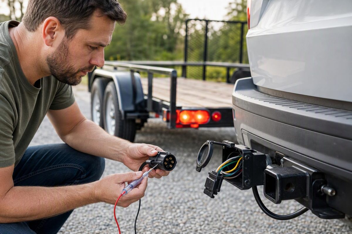
Before replacing a trailer plug, test the vehicle socket with the trailer disconnected, then test the connected circuit under load. Unloaded voltage alone does not prove the socket can power the lamps. Replace the plug only when testing or inspection identifies damaged contacts, terminal attachments or housing; a ground, wire or vehicle-output fault needs a different repair.
This procedure covers common North American 12 V light-trailer connections. Treat electric-brake output separately from lighting output.
Select the finding you have verified; use the result to choose your next test or repair.
Choose The Next Diagnostic Step
Use loaded-loss findings only with current flowing. Compare losses with equipment service limits; no universal cutoff is supplied. Electric brakes need a separate controller-specific test.
Fault Not Yet Located
Inspect with power off, then test the disconnected vehicle socket. A symptom alone is not enough to condemn the plug.
Findings And Next Steps
| Verified Finding | Points Toward | Next Step |
|---|---|---|
| Output only with verified vehicle ground | Socket-ground fault | Inspect and test the socket’s ground path. |
| No unloaded output with verified ground | Vehicle output or test conditions | Follow vehicle test conditions; check trailer fuse, harness, converter or towing module. |
| Unloaded socket output present | Loaded fault still possible | Connect the trailer; measure ground and feed losses with lamps carrying current. |
| Excessive loaded ground-return loss | Return-path fault | Split the test across lamp ground, trailer ground wiring and mated ground contacts. |
| Loaded feed loss across connector | Contacts or terminal attachments | Isolate power; inspect both connector halves and attached terminals before choosing parts. |
| Loaded feed loss from plug to lamp | Trailer wiring or splices | Test shorter feed sections to locate the loss. |
| Vehicle feed falls under trailer load | Vehicle supply path or trailer load fault | Use the vehicle service procedure; include overload and short checks. |
| Correct voltage across an unlit lamp | Bulb, holder or lamp assembly | Check the lamp components rather than replacing the plug. |
| Zero drop with no current | Inconclusive test | For an open wire, isolate power and disconnect the section before resistance testing. |
Sources: etrailer’s 4-/5-way troubleshooting guide and Fluke’s voltage-drop and resistance guidance, linked in the article. Applies to common North American 12 V trailer lighting.
Identify The Connector And Diagram View Before Probing
The plug is normally on the trailer; the socket is on the tow vehicle. Count the contacts and identify their shape—not just the shape of the outer housing.
| Connector Family | Common Circuit Functions |
|---|---|
| 4-way flat | Ground, running lights, left turn/stop, right turn/stop |
| 5-way flat | The four basic circuits plus reverse lights or surge-brake reverse lockout |
| 6-way round | Basic lighting and ground, electric-brake output, auxiliary 12 V supply |
| 7-way RV blade | Basic lighting and ground, electric-brake output, auxiliary 12 V supply, reverse lights |
These are common arrangements, not proof of how an unknown trailer is wired. CURT’s wiring reference distinguishes round-pin and RV-blade seven-way connectors and shows different wire-color conventions. etrailer’s troubleshooting guide also identifies the fifth circuit’s reverse-lockout use and covers the inspection, socket and converter checks below.
Match the diagram’s viewing side. The front mating face is where the contacts meet; the rear wire-entry view is where the wires attach. Looking from the opposite side reverses the layout. Record the key or latch position before assigning terminals.
Use the appropriate 7-way diagram and orientation guide or 6-pin connector map. Verify circuit function rather than copying colors from the old plug.
Inspect Contacts, Terminals And Cable With Power Off
Park securely, apply the parking brake and chock the trailer. Disconnect the trailer plug and switch off the relevant circuits before opening a serviceable connector. Isolate any trailer battery or other supply feeding the wiring you will handle.
Inspect both halves for:
- Corrosion, moisture or dirt on the contacts.
- Bent, loose or recessed contacts and broken retaining features.
- Loose wires or terminals inside a serviceable plug.
- Cracked housing, heat damage or a failed cable clamp.
- Cuts and chafing along the cable, especially near moving parts.
Also check the affected bulb or lamp assembly for damage. Photograph and label verified terminal functions before disconnecting wires.
Test The Vehicle Socket Without The Trailer
Use a connector tester intended for that socket and vehicle system, or a digital multimeter set to DC volts. For voltage measurements, put the leads in COM and V, not the current-measurement jack. Use probes that will not spread contacts or bridge adjacent terminals.
With the black probe on the identified socket ground, have a helper operate one lighting function at a time:
| Function Operated | Expected Socket Output |
|---|---|
| Running lights | Voltage on the running-light terminal |
| Left turn | Pulsing voltage on the left turn/stop terminal |
| Right turn | Pulsing voltage on the right turn/stop terminal |
| Brake pedal, turns off | Voltage on both combined turn/stop terminals |
Compare steady lighting readings with the vehicle supply voltage under the same operating conditions; do not assume it must be exactly 12.0 V. A meter’s display may lag a flashing signal.
If an output is absent, repeat the measurement using a verified vehicle ground. An output that appears only with that reference points toward a socket-ground fault. If it remains absent, follow the vehicle-specific test conditions and check the trailer fuse, harness connections, converter or towing module. Working vehicle lamps do not prove the trailer outputs work.
Passing this test verifies unloaded output only. It does not clear the socket or vehicle harness of a fault that appears under load.
Measure The Ground Return With The Lamps Operating
Reconnect the trailer and turn on the affected lamps. Use a suitable breakout lead or approved back-probing method without damaging seals or contacts.
To measure ground-side voltage drop:
- Place the red probe on the affected lamp’s ground terminal.
- Place the black probe on a verified vehicle ground, using an extension lead if necessary.
- Read DC volts while the lamp circuit is switched on and carrying current.
This measures voltage lost along the return path. A healthy return should be close to 0 V; use the equipment’s service limits where available. There is no universal numeric pass/fail limit supplied here. Fluke’s automotive troubleshooting guidance explains that voltage-drop testing requires current flow and describes measuring across wires and connections to locate losses.
If the loss is excessive, test smaller sections: lamp ground to trailer ground point, trailer ground point to plug ground, and across the mated ground contacts. The section accounting for the loss needs attention.
Lamps that dim or misbehave when running lights and brake lights operate together make a shared-ground fault worth checking, but overloads can produce similar symptoms. etrailer’s guide lists both possibilities; the symptom alone does not identify the failed part.
Locate Feed-Side Loss Before Replacing The Plug
With the affected circuit still operating, measure voltage drop across each accessible section of its feed path. Across a mated connector, place the red probe on the vehicle-side feed and the black probe on the matching trailer-side feed. Then test from the trailer-side feed to the lamp’s positive terminal.
A loss concentrated across the connector points to its contacts or terminal attachments. A loss farther along the trailer points to wiring or splices. If neither accounts for the low lamp voltage, recheck the vehicle-side socket feed against a verified vehicle ground with the trailer load connected. If that feed falls under load, investigate the vehicle supply path, converter or module using its service procedure, including checks for trailer overload or a short.
Gently move the cable near the plug while watching the reading. A change helps locate an intermittent fault, but does not distinguish a loose terminal from broken strands by itself.
A zero-drop reading does not clear a circuit with no current flowing. For an open wire, disconnect and isolate the section before checking resistance or continuity. Never use resistance mode on energized wiring. Fluke’s resistance instructions require power off and warn that parallel paths affect readings. A continuity beep also does not prove the wire can carry its operating load.
If the correct operating voltage reaches the lamp across its positive and ground terminals but it remains out, check the bulb, holder or lamp assembly rather than replacing the trailer plug.
Test Electric-Brake Output By The Controller’s Procedure
Do not expect full brake-output voltage simply because the pedal is pressed while parked. Proportional controllers respond to deceleration; follow the exact controller’s diagnostic and manual-control procedure.
For example, the Tekonsha P3 manual provides brake-output voltage and current diagnostics and warns that some test lights or non-Tekonsha testers can trigger an output-short warning. A basic lighting tester is not a universal brake-controller tester.
Replace The Failed Parts And Verify Combined Loads
Replace a connector with damaged contacts, broken retention or heat-damaged housing rather than relying on cleaning alone. If corrosion or damage extends into the cable, replacing only the plug leaves the fault behind.
Choose the replacement by mating family, verified terminal functions, wire-size acceptance and manufacturer circuit ratings. Switch off and isolate supplies again before repair. Reassemble to the connector’s instructions, secure the cable clamp, and leave enough slack for turns without letting the cable drag or catch in the chains.
Before towing, test left turn, right turn, stop and running lights individually, then together to expose shared-return problems. Verify brakes separately where fitted. CURT’s hookup guidance calls for a complete light-function check and cable routing that avoids tension, pinching and dragging.