
20 min read ·
How to Protect a Connector Without Hiding a Bad Connection
It can help preserve a connection that is already clean, dry, tight, correctly assembled and compatible with the product.
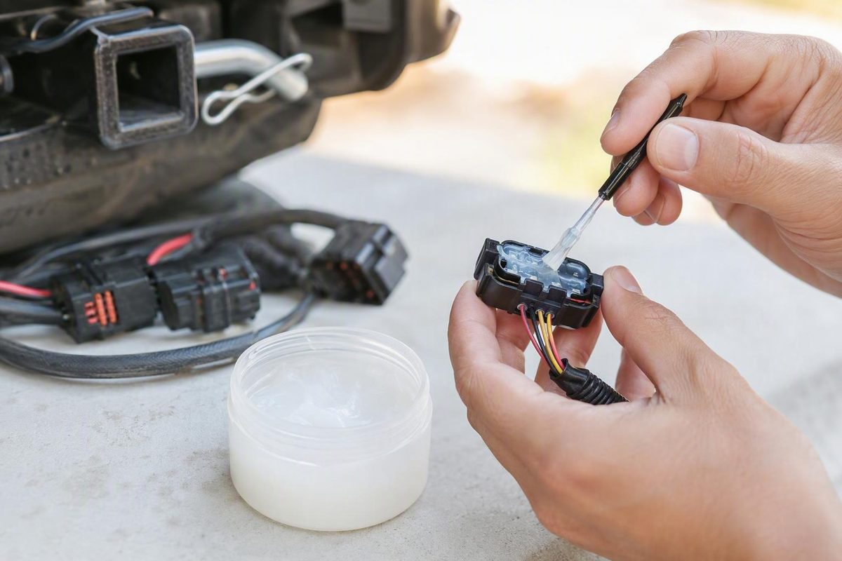
Silicone dielectric grease creates a protective barrier around an electrical connection. It does not create the connection itself.
That distinction resolves most confusion about the product. Dielectric grease is electrically insulating, yet it can coexist with a reliable circuit when clean, correctly fitted terminals make firm metal-to-metal contact. Contact pressure and wiping action can displace grease at the loaded contact points, leaving the remaining material around the joint to help exclude moisture and contamination.
Connector condition comes first. Corrosion, weak terminal tension, loose crimps, backed-out contacts, damaged seals, and poor fit should be corrected before grease is applied. Otherwise, grease may conceal contamination or complicate an already marginal connection.
This is a conservative introductory guide rather than a connector-family service specification. Available evidence includes manufacturer product information, commercial editorial guidance, practitioner experience, and forum anecdotes—not controlled testing across every connector design. Equipment-manufacturer procedures, connector specifications, technical data sheets, safety data sheets, and compatibility documents take priority.
What silicone dielectric grease does—and does not do
Silicone dielectric grease is a viscous, electrically insulating compound used to protect electrical components and connections. Products in this category are commonly silicone-based, but individual formulations vary. The category name alone does not establish viscosity, additives, dielectric properties, operating limits, curing behavior, or compatibility with a particular plastic, elastomer, seal, or wire insulation.
Its primary job is environmental protection. Applied appropriately to a clean, dry connection, it can form a barrier around the joint and reduce exposure to moisture, oxygen, dirt, salt, and grime. The Drive describes dielectric grease as a nonconductive protectant, commonly silicone-based, and distinguishes it from ordinary lubricating grease (The Drive’s guide to dielectric grease).
What silicone dielectric grease does not do is equally important:
- It does not conduct current through the bulk grease.
- It does not create terminal pressure.
- It does not restore contact material lost to corrosion or overheating.
- It does not repair a loose crimp, bent pin, cracked housing, or damaged seal.
- It does not make an open circuit close.
- It does not turn an incompatible or poorly assembled connector into a reliable one.
An electrical connection does not require dielectric grease to function. Current flows because compatible conductors are held together with enough force over a suitable contact area. The grease is optional protection for that joint, not a necessary part of the conductive path.
Do not treat dielectric grease and general-purpose mechanical grease as interchangeable. Wheel-bearing, chassis, and other mechanical greases are formulated for different loads and environments. Their base oils, thickeners, and additives may not be appropriate for connector housings, seals, insulation, or closely spaced electrical contacts.
“Non-curing” is also a product-specific characteristic rather than a universal definition. Super Lube, for example, describes its silicone dielectric and vacuum grease as non-curing, but that statement applies to the named formulation rather than every silicone dielectric grease (Super Lube product information).
Expectations should reflect the limits of the evidence. Manufacturer pages can document what a company claims for its own product, but they are not independent performance studies. Commercial guides and practitioner articles can explain mechanisms and identify possible failure modes, while forum discussions can illustrate real-world disagreements. None substitutes for testing or instructions specific to the connector being serviced.
Why a nonconductive grease can work in a sound connector
The apparent contradiction disappears when the connector is viewed as a mechanical assembly: current passes through direct metal-to-metal contact, not through the surrounding grease.
A typical weather-resistant connector includes:
- A housing that aligns and supports the mating halves
- An interface seal between those housings
- Individual cavities that guide and separate the terminals
- Matching male and female terminals
- A wiping zone where the terminal surfaces slide together
- A protected area around, behind, and beside the loaded contact points
When a properly formed female terminal grips a matching male terminal, spring force presses their conductive surfaces together. As the connector mates, the surfaces slide across one another. That wiping action can move grease away from the microscopic points carrying current while leaving grease around the contact area.
A clamped electrical joint follows a related principle. The prepared conductors must first be brought into firm contact by the clamp or fastener. Any protective compound around that joint is secondary to the mechanical force establishing the connection.
This explanation depends on important assumptions:
- The contacts are clean and serviceable.
- The terminal pair is correctly matched.
- The contacts are straight and fully seated.
- Terminal retention is intact.
- The female contact still has adequate spring force.
- The connector follows its intended mating path.
- The amount of grease does not prevent full assembly.
When those conditions are absent, grease may remain across part of a weak interface. A loose, oxidized, worn, bent, or backed-out terminal may have too little pressure or wiping distance to establish stable contact.
That is why “never put dielectric grease on pins” and “always pack the connector” are both poor universal rules. Placement depends on connector design and the applicable service instructions. Some procedures may permit treatment of mating areas or cavities, while others may limit the compound to a seal, boot, ceramic interface, or exterior surface.
A trailer-forum discussion illustrates the uncertainty without proving causation. One user reported losing all trailer lights after treating a seven-way plug, then later identified oxidation, loose fit, and inadequate wiping force as possible contributors; cleaning reportedly restored operation. Other users described trouble-free use. The account supports inspecting connector condition, not the conclusion that grease alone caused the failure (Forest River forum discussion).
A trade-publication article likewise describes an intermittent instrument-cluster connection that worked after grease removal, cleaning, drying, and application of another compound. Because several variables changed during the repair, the case cannot identify which step resolved the fault. It remains useful only as an example of why grease should not be expected to compensate for marginal contact pressure (GCMOnline’s dielectric-grease discussion).
Inspect first: protect, repair, replace, or check the manual
The following four-outcome framework is a conservative screening tool, not a substitute for connector-specific acceptance criteria.
1. Clean and protect
Consider protective treatment only when the connector is fundamentally sound:
- Contacts are clean and dry.
- Visible terminal surfaces are free of significant corrosion.
- Pins and sockets are straight.
- Terminals sit at consistent depths and remain retained.
- Mating halves fit firmly and lock completely.
- Crimps appear secure.
- Required seals and cavity plugs are present.
- There is no visible burning, melting, cracking, or substantial plating loss.
If removable contamination is present, use a cleaning method approved for the connector materials. Allow the assembly to dry completely before applying any grease, and treat only the locations permitted by the relevant instructions.
2. Repair
Repair may be appropriate when the connector is serviceable and approved replacement parts, tools, and procedures are available. Possible correctable faults include:
- A backed-out terminal
- A loose or incorrectly formed crimp
- A replaceable contact with weak retention or spring force
- A displaced secondary lock
- A missing cavity plug
- A damaged replaceable seal
- Incorrect wire fit at a rear grommet
- An assembly error that can be corrected without damaging the housing
Do not simply push a backed-out terminal forward and consider the work complete. Determine why it moved.
Correct contacts, sound crimps, full terminal seating, intact seals, and proper mating fit matter more than adding grease.
3. Replace
Replacement is the conservative choice when hardware can no longer provide a reliable mechanical and electrical joint. Warning signs include:
- Heavy green or white corrosion
- Pitted or missing contact material
- Burned or discolored terminals
- Melted or badly distorted plastic
- Bent contacts that cannot be restored under an approved procedure
- Worn or spread female contacts
- Cracked housings
- Broken latches or terminal-retention features
- Contamination or moisture that has migrated into the wire
- Repeated intermittency after proper cleaning and assembly
Grease can cover corrosion but cannot reverse it. It can surround a weak terminal but cannot restore spring force. Sealing visibly damaged hardware only makes the defect harder to inspect.
4. Follow manufacturer guidance
Obtain application-specific instructions before treating safety-critical, high-voltage, high-current, arcing, hot-switched, RF, relay, switch, or electronically sensitive connections. Examples include restraint wiring, vehicle high-voltage systems, control-module connectors, RF interfaces, relay contacts, and heavily loaded power joints.
An experienced practitioner’s technical discussion similarly recommends following manufacturer instructions for switches and relays and treating arcing, high-power, and RF applications cautiously (technical discussion of dielectric and conductive grease).
Whatever the outcome, visible corrosion, salt, dirt, and other contamination should be removed before protection is added. Applying grease over water or debris does not remove the contamination; it encloses it.
A conservative step-by-step application method
There is no evidence-supported universal dose for every terminal shape, cavity size, seal design, and grease viscosity. Use the following as a cautious general workflow, then defer to the connector and equipment makers.
Step 1: Isolate the equipment as directed
Use the equipment manufacturer’s shutdown and isolation procedure before separating a connection. This article does not provide a universal isolation sequence.
If the correct procedure is unavailable, the circuit is safety-critical, or the work is outside your competence, stop and obtain qualified help rather than experimenting.
Step 2: Separate and inspect the connector
Release the connector using its designed latch rather than pulling on the wires. Examine both halves under good lighting.
Look for:
- Green, white, dark, or crusted contamination
- Water, salt, mud, or dust
- Bent, recessed, or backed-out terminals
- Loose mating fit
- Cracked housings or broken locks
- Loose or visibly poor crimps
- Damaged interface or wire seals
- Missing cavity plugs
- Heat discoloration or melting
Treat that comparison as a troubleshooting clue, not a substitute for the connector maker’s dimensional specification.
Step 3: Clean with a compatible method
Use a cleaner and process approved for the connector’s metals, plating, housing, seals, adhesives, insulation, and markings. No universal solvent can be prescribed for every connector or grease formulation.
If corrosion has pitted a contact or reduced its mechanical integrity, replacement is generally more defensible than repeated abrasion.
Step 4: Let the assembly dry fully
Do not cover residual water or cleaner with grease. Inspect blind cavities and rear wire entries as well as the visible connector face.
Use only drying methods permitted by the applicable service information. A generic instruction cannot establish whether compressed air, heat, or another drying process is acceptable for a particular housing or seal system.
Step 5: Verify fit, retention, and contact action
Before adding grease, check that:
- Each terminal remains retained.
- The connector follows its normal mating path.
- The contacts engage firmly.
- The primary latch and any secondary lock operate correctly.
- The seal sits evenly.
- The connector can close fully without abnormal force.
If the connector already feels loose, grease is not the next repair step. Correct the fit problem or replace the affected hardware.
Step 6: Apply a thin, controlled film
Apply the product only where the connector or equipment maker permits it. Depending on the design, that might be a boot, seal, ceramic interface, cavity wall, exterior surface, or mating area.
Avoid large globs, pools, and indiscriminate flooding. More grease does not create more contact pressure.
A tube usually gives the best placement control. A packet is convenient for a field kit or one-time task, although it may contain more material than a small connector needs. A spray can reach awkward areas but increases overspray and introduces formulation-specific handling requirements. Consult the exact product label and safety data sheet rather than transferring precautions from another aerosol.
Step 7: Reconnect, lock, clean up, and test
Mate the connector straight and fully without forcing it past an obstruction. Engage every required latch or secondary lock. Remove displaced excess from exterior areas where it could collect dirt or interfere with inspection.
Restore operation under the equipment maker’s procedure and test every relevant function. If a circuit fails, isolate the equipment again and reinspect the connection rather than repeatedly forcing the halves together.
Where it belongs in common automotive, trailer, and low-voltage jobs
These examples show conservative placement principles, not universal service instructions. Connector-family and OEM documentation overrides them.
Spark-plug boots
Clean and dry the rubber boot and the spark plug’s ceramic insulator. Where the product and ignition-system instructions permit it, use a small amount around the boot’s inner wall or at the boot-to-ceramic interface rather than indiscriminately packing the metal terminal junction. The Drive describes this controlled boot application after cleaning the plug and boot (spark-plug boot application guidance).
Confirm that the boot seats normally. A loose terminal, damaged boot, cracked ceramic, deteriorated lead, or visible tracking requires diagnosis or replacement rather than additional grease.
Seven-pin trailer plugs
Inspect the plug and socket before treatment. Remove removable contamination, let the parts dry, and check each contact for looseness, wear, movement, or heat damage.
Physical fit matters. A plug that mates with little retention or works only when held at an angle has a mechanical problem. Grease will not restore terminal tension.
If the connector maker permits treatment, apply controlled coverage rather than flooding the plug. Reconnect it fully, secure the retainer, and test each installed lighting and brake-related circuit. Outdoor plugs also merit periodic inspection because they encounter water, road grime, salt, and repeated mating cycles.
Battery terminals
Create the electrical joint first:
- Follow the equipment maker’s battery-service procedure.
- Clean the mating surfaces using an approved method.
- Inspect the post, clamp, cable, crimp, and insulation.
- Replace damaged or badly corroded parts.
- Assemble and tighten the joint according to the specified procedure.
Only after a clean, tight metal-to-metal clamp connection exists should dielectric grease be considered for surrounding or external protection. Do not rely on grease placed between loose clamped surfaces to make the circuit reliable.
For aerosol products, consult the exact label and safety data sheet for handling and use around the battery. Formulation-specific precautions should not be generalized from another product.
Bulb sockets
With the equipment isolated under its service procedure, remove the bulb and inspect the socket. Clean removable oxidation without changing the contact shape. Check whether the spring contact still presses firmly and whether the socket is burned, distorted, or brittle.
Where approved, use a light protective coating, install the correct bulb fully, and test operation.
Weather-sealed multipin connectors
Inspect more than the visible pin faces. Useful checks include:
- Terminal seating
- Primary and secondary locks
- Plugs in unused cavities
- Interface seals
- Rear wire seals or grommets
- Wire fit
- Crimp condition
- Housing alignment
Follow the connector maker’s instructions on whether seals, cavities, or contact areas may be treated.
Marine and other outdoor connectors
Begin with a dry, undamaged connection. Remove salt residue, water, grime, and other contamination before adding protection.
Covers and strain relief remain important; grease should not be expected to compensate for a plug left in standing water or a cable continually pulling on its terminals.
A commercial marine guide recommends inspection, cleaning, complete drying, and a thin film rather than pooling. It also distinguishes the access advantage of sprays from the better placement control of tubes (Boat Juice application guide). Because that source is a retailer’s article rather than a connector specification, product and equipment documentation still controls.
O-rings and rubber parts
Do not assume every silicone grease is compatible with every elastomer. Use it on an O-ring, boot, grommet, or seal only when the product maker’s compatibility information supports the material and the connector maker permits treatment.
Consider a spot test only when the product maker allows it and replacing the part would not be safer. Stop if the material softens, swells, discolors, or becomes tacky.
Troubleshooting a connection that fails after greasing
If a circuit becomes intermittent or stops working after grease is applied, do not assume either that the grease caused the failure or that it could not have contributed. Treat the timing as a clue and inspect the complete connection.
1. Establish what changed
Document the condition before and after service as accurately as possible:
- Was the connector already loose?
- Was corrosion visible?
- Were contacts cleaned, bent, or disturbed?
- Was a wire pulled?
- Did a terminal move backward?
- Was the intended product used?
- Was the connector fully latched afterward?
- Did one circuit fail, or did several fail together?
These are diagnostic starting points, not proof of a particular fault.
2. Isolate and separate the connection
Use the equipment maker’s procedure, then release the housing by its latch rather than pulling on the wires.
If the halves resist full assembly, inspect for an obstruction, misalignment, damaged seal, backed-out terminal, or excessive product. Do not force the connector.
3. Remove excess product compatibly
Use a removal method approved for both the grease and the connector materials.
Remove heavy deposits and inspect underneath them for water, dirt, salt, corrosion, or cleaner residue. The absence of visible contamination on top of the grease does not establish that the interface beneath it is clean.
4. Inspect mechanical contact quality
Look for:
- Weak terminal spring force
- Loose male-to-female fit
- Bent or spread contacts
- Backed-out terminals
- Broken latches or secondary locks
- Loose crimps
- Damaged wire strands
- Heat discoloration
- Damaged or displaced seals
- Incorrectly matched terminals
Where appropriate, observe retention carefully or follow the connector maker’s terminal-position test.
5. Clean, dry, repair, and retest
Clean the assembly using an approved process, let it dry, and repair or replace defective hardware. Reconnect without forcing it, engage every lock, restore operation under the applicable procedure, and test each affected function.
If electrical measurements are required, use the equipment maker’s limits and test method.
How to interpret failure anecdotes
The trailer-light account is useful because the poster later identified oxidation, loose fit, and weak wiping action as possible contributors and reported that cleaning restored operation. It does not prove that silicone dielectric grease was the sole cause.
The instrument-cluster account involved grease removal, cleaning, drying, and application of a conductive compound. The reported repair succeeded, but several variables changed at once. It should therefore be treated as a single repair anecdote rather than a controlled comparison.
Excess grease can nevertheless complicate troubleshooting. It may increase insertion resistance, conceal a backed-out contact, hold debris in a cavity, or remain across a terminal pair with inadequate pressure. Those are reasons to control the amount—not evidence that every properly treated connector will fail.
For high-voltage, high-current, safety-critical, RF, arcing, hot-switched, or control-module circuits, stop and obtain the applicable manufacturer procedure or qualified assistance.
Dielectric grease versus cleaners, conductive compounds, and substitutes
Products used around electrical connections are not interchangeable merely because they come in similar tubes or spray cans.
| Product category | Primary job | Key limitation |
|---|---|---|
| Contact cleaner | Remove contamination where the product and connector maker permit it | Usually does not provide the same persistent barrier as grease |
| Silicone dielectric grease | Protect a clean, sound connection from moisture and contamination | Does not create conductivity or repair contact pressure |
| Conductive or metal-filled compound | Serve a specified contact or joint application | Misplaced material may create unintended paths between circuits |
| Ordinary mechanical grease | Lubricate bearings, pivots, or other mechanical components | Composition may be unsuitable for connectors and seals |
| Petroleum jelly | Provide a petroleum-based barrier or lubricant in selected uses | Not compositionally identical to silicone dielectric grease |
| Anti-oxidation compound | Limit oxidation in specified conductors and joint designs | Must match the conductor and connection system |
| Water-displacing spray | Displace moisture or provide the protection stated on its label | Not automatically a substitute for connector grease |
Contact cleaner
Contact cleaner is used first, where approved, to remove contamination. Dielectric grease comes afterward only if the restored connector is dry, mechanically sound, compatible, and approved for treatment.
Cleaner does not restore a terminal that has lost spring force. Grease does not remove oxide already occupying the interface. The products address different parts of the problem.
Conductive or metal-filled grease
Conductive compounds are a separate category. Some contain copper, carbon, silver, or other particles. Their suitability depends on the intended joint.
Do not treat conductive grease as a universal upgrade. In a closely spaced multipin connector, misplaced conductive residue may create an unintended path between circuits.
Use conductive compounds only where the connector or equipment maker explicitly permits the selected product.
Petroleum jelly
Petroleum jelly is not the same formulation as silicone dielectric grease. It may be used successfully in selected applications, but the available evidence does not establish universal equivalence in temperature behavior, longevity, water resistance, or compatibility.
Anti-oxidation compounds and water-displacing sprays
Anti-oxidation compounds are commonly selected for particular conductor materials and joint designs. Water-displacing sprays have their own moisture-management and protective uses as described by their manufacturers.
Neither should be selected as a blanket replacement for silicone dielectric grease based solely on a forum report. Choose a product according to connector design, materials, environment, and manufacturer instructions.
How to choose a product and verify its limits
Start with the application, not the product label. A useful buying checklist includes:
- Intended uses: Does the manufacturer identify connectors, boots, sockets, seals, or the specific application?
- Formulation: Is the product explicitly described as silicone dielectric grease?
- Curing behavior: Does the maker call the product non-curing, or does it change after application?
- Format: Is a tube, packet, cartridge, tub, or aerosol appropriate?
- Technical data sheet: Are electrical, thermal, physical, and environmental properties documented?
- Safety data sheet: Are product-specific handling and storage instructions available?
- Compatibility information: Are relevant plastics, elastomers, insulation, and seal materials addressed?
- Package size: Can the container remain clean and controllable during its useful life?
- Application control: Can a thin film be placed without flooding adjacent areas?
Choose the format deliberately
Tubes usually provide the most precise placement. They suit accessible boots, seals, sockets, and connector faces.
Packets are portable and convenient for field kits, although one packet may contain more grease than a small connection requires.
Aerosols can reach awkward areas but reduce placement control and increase the possibility of overspray. Consult the exact product label and SDS for handling, ventilation, storage, ignition-source, and battery-area instructions rather than generalizing across formulations. A commercial application guide likewise emphasizes thin coverage and the different control characteristics of sprays and tubes (format and application discussion).
Verify specifications product by product
Check the manufacturer’s documentation for:
- Operating-temperature range
- Dielectric properties
- Water resistance or washout performance
- Viscosity or consistency
- Plastic compatibility
- Elastomer and O-ring compatibility
- Wire-insulation compatibility
- Vacuum suitability, if relevant
- Storage and shelf-life conditions
- Approved application methods
A rating published for one formulation applies only to that product under its stated test conditions. It is not a category-wide specification.
AGS markets its Dielectric Silicone Grease for electrical and electronic connections and offers it in 1.25-ounce and 4-ounce tubes. Those are manufacturer-stated product details, not proof that the formulation suits every connector or operating environment (AGS Dielectric Silicone Grease).
Super Lube describes its silicone dielectric and vacuum grease as non-curing and lists packages beginning with a 3-ounce tube, followed by larger commercial containers. The company also states that the product is NSF H1 registered for incidental food contact under applicable conditions. That registration does not make the grease food and is not evidence of superior electrical performance (Super Lube product information).
For unusual or aged seals, consider spot-testing only when the product maker permits it and replacement is not the safer option. Stop using the compound if the material softens, swells, becomes tacky, or otherwise changes.
The larger lesson is to buy documentation, not merely a label. “Silicone dielectric grease” identifies a product category; it does not answer every question about where a particular formulation belongs.
Frequently asked questions
Is silicone dielectric grease electrically conductive?
No. Silicone dielectric grease is electrically insulating in bulk. Current passes through direct metal-to-metal contact between properly fitted terminals, not through the grease.
In a sound connector, contact pressure and wiping action can displace grease at the loaded points while leaving protection around them. The grease does not improve conductivity or make an open connection close.
Can silicone dielectric grease go directly on connector pins?
Sometimes, but not as a universal rule. Placement depends on the connector design, product compatibility, and manufacturer instructions.
Direct application assumes clean contacts, adequate terminal pressure, proper wiping action, and a controlled quantity. Some procedures may permit grease on mating areas or in cavities; others may restrict it to seals, boots, or surrounding surfaces. Avoid flooding a connector when application-specific instructions are unavailable.
Can too much dielectric grease cause a bad connection?
Excess grease can contribute to problems in a marginal or unsuitable connector. It may resist full insertion, obscure backed-out contacts, collect contamination, or remain between contacts that lack enough pressure or wiping action to displace it.
That does not establish grease as the sole cause of every post-application failure. Corrosion, weak terminals, bent pins, damaged locks, and poor crimps may coexist. Remove excess compatibly, inspect the entire assembly, repair defects, reconnect, and test.
Should I use silicone dielectric grease on a seven-pin trailer plug?
It can provide controlled environmental protection when the plug is clean, completely dry, mechanically sound, compatible with the product, and approved for treatment.
First inspect for corrosion, weak terminal fit, movement in the housing, and heat damage. Apply only a thin amount where permitted, reconnect the plug fully, and test every installed lighting and brake-related circuit. Repair or replace a loose plug before adding grease.
Is dielectric grease the same as contact cleaner or conductive grease?
No. Contact cleaner removes contamination where its use is approved. Dielectric grease is an insulating protective barrier applied afterward, when appropriate, to a clean and dry connection.
Conductive grease is a different category and may contain conductive particles. Misplaced material can create unintended paths in closely spaced circuits, so it should not replace dielectric grease without application-specific approval.
The safest rule is condition-first: silicone dielectric grease can help preserve a connection that is already clean, dry, tight, correctly assembled, and compatible with the product. It cannot create the metal-to-metal contact the circuit requires. When in doubt, repair the terminal or follow the connector or equipment maker’s instructions before adding a thin protective film.