
22 min read ·
What to Know Before Using or Replacing an Old MaxBrake
Treat an installed or secondhand MaxBrake as unsupported until its identity, condition, wiring, pressure sensor and brake-system installation are verified.
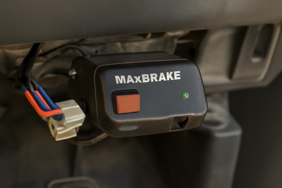
An installed or secondhand MaxBrake trailer brake controller should be treated as an unsupported legacy system until its identity, condition, wiring, pressure sensor, and brake-system installation have been verified. Historical sources describe hydraulic and air-brake versions that used tow-vehicle brake pressure as the control input, but surviving documentation is incomplete, model distinctions remain unclear, and many performance claims come from promotional material or owner anecdotes.
That makes an old MaxBrake more than a routine controller-wiring project. Its installation may include a pressure sensor and tee added to safety-critical hydraulic or air-brake plumbing. Before towing, identify the exact unit, have any modified brake plumbing professionally assessed, verify every electrical circuit, and use only instructions that can be tied reliably to that version.
If replacement is appropriate, choose a currently supported controller by documented compatibility with the vehicle, trailer brakes, actuator, axle count, and electrical system—not by claims that one product is the “closest” MaxBrake equivalent.
Related: Deutsch Connector Kits: What’s in Them & How to Crimp DT Right.
MaxBrake at a glance: what it was and where availability stands
Multiple historical third-party sources describe MaxBrake as a trailer brake controller that varied electric trailer-brake output in response to hydraulic pressure in the tow vehicle’s braking system. Material directed at converted heavy-duty-truck owners also describes an air-pressure version.
The surviving record is fragmented. A December 26, 2009 Wayback Machine capture of a MaxBrake Controller page confirms that the archived URL existed, but its extracted contents contain no readable specifications, instructions, prices, or product claims. The URL and title establish the existence of a page, not what any particular controller could do.
The available status evidence can be summarized cautiously:
- 2008: A TractorByNet participant described an installation involving a tee and pressure sensor at a master-cylinder brake-line connection. The participant reported an approximate package price of $319 and said the product website advertised about one hour of installation time. These were secondhand reports, not verified pricing or a safe labor estimate for another vehicle. The 2008 discussion preserves the reported price and installation description.
- 2011: Dealer availability was disputed. One Diesel Truck Resource user reported that Southwest Wheel no longer listed MaxBrake; another said the MaxBrake website still identified that business as a dealer. The thread did not establish why the listing changed or whether the product remained broadly available. The 2011 discussion documents those conflicting reports.
- 2015: The opening post in a Turbo Diesel Register knowledge thread stated that MaxBrake and the earlier BrakeSmart were no longer in business. That was a forum assertion rather than a manufacturer announcement or corporate record. The dated thread preserves the claim and reproduced technical material.
- 2017: A Good Sam forum user said MaxBrake and Smart Brake were no longer in production. Separately, a Heavy Haulers RV Resource Guide page reported that MaxBrake was no longer available and that the company had gone out of business. Both remain third-party reports rather than definitive evidence of an exact closure or discontinuation date. The Good Sam post records the production claim.
- Current retailer listing: Camaro Central identifies part BRC-255 as a hydraulic-over-electric MaxBrake controller and marks it “Currently Unavailable.” The listing does not say when availability ended or establish the status of every MaxBrake product. The BRC-255 listing shows the retailer’s current designation.
These reports support treating MaxBrake as a legacy product whose normal retail availability ended years ago. They do not establish an exact discontinuation date, the manufacturer’s present legal status, or whether isolated manuals, sensors, harnesses, repair services, new-old-stock parts, or used controllers remain available. One retailer’s unavailable listing also does not prove that no inventory exists anywhere.
Current factory or third-party technical support should therefore be considered unverified rather than assumed. Keep an installed or secondhand controller out of towing service until its exact version, documentation, physical condition, wiring, calibration requirements, and pressure-sensor installation have been assessed.
How pressure-sensing brake control differs from other controller types
A trailer brake controller regulates electrical output to compatible trailer brakes. Controller families differ primarily in how they determine braking demand.
Historical MaxBrake descriptions present this general concept:
- The driver applies the tow vehicle’s brakes.
- A sensor responds to pressure in a hydraulic brake circuit or, for an air-brake application, an appropriate air circuit.
- The cab-mounted controller interprets the pressure signal.
- The controller varies trailer-brake output according to that signal and its configuration.
That differs from two common controller categories:
- A time-delay controller begins increasing trailer-brake output after receiving a brake-activation signal. Its output rises according to a timed progression rather than direct measurement of hydraulic pressure or vehicle deceleration.
- A conventional proportional or inertia-based controller generally uses an accelerometer to respond to vehicle motion or deceleration.
CURT’s general controller guide explains the time-delay-versus-inertia distinction and discusses gain, sensitivity, manual activation, and controlled testing. It is useful background, but it is not a MaxBrake calibration manual.
The practical distinction is the source of the demand signal:
| Controller approach | Primary input used to determine braking demand |
|---|---|
| Pressure sensing | Hydraulic or air-brake pressure |
| Time delay | Brake activation followed by a timed output progression |
| Inertia-based proportional | Measured vehicle motion or deceleration |
| Vehicle-data controller | Information obtained through a compatible vehicle interface |
| Factory-integrated system | Vehicle-specific data and controls defined by the vehicle manufacturer |
A different input method does not automatically make one design better. Pressure sensing responds to brake-system pressure even when measured deceleration is modest. Inertia sensing observes vehicle motion without requiring an aftermarket pressure tap in the tow vehicle’s brake plumbing.
Historical promotional material depicts a MaxBrake manual trailer-brake lever, calibration control, sensitivity adjustment, and hydraulic or air-pressure sensor packages. These details help explain the product concept but do not prove that every version had the same faceplate, controls, diagnostics, adjustment range, firmware, or trailer compatibility. The promotional MaxBrake page illustrates the reported architecture and controls.
Pressure input drew particular interest from some converted heavy-duty-truck owners. A July 5, 2017 Heavy Haulers RV Resource Guide page argued that a very heavy truck might not produce the deceleration or nose-dive response expected by an inertia controller even while its service brakes were being applied. That was the resource’s analysis, not a controlled comparison across multiple trucks, loads, controllers, and road conditions. The heavy-truck resource explains that reasoning and identifies the reported air-brake kit.
The available evidence does not establish that MaxBrake necessarily followed ABS modulation, shortened stopping distance, prevented wheel lockup or jackknifing, or was safer than current controllers. Braking behavior depends on the entire system, including vehicle and trailer compatibility, loading, setup, brake adjustment, wiring, tires, road surface, component condition, and driver input.
Identify the exact controller before relying on any instructions
“MaxBrake” is not a sufficiently precise identification for wiring, calibration, or compatibility decisions. At least three identifiers appear in surviving material, and the evidence does not define how they relate to one another.
Before connecting power or moving the vehicle, record:
- Full label text: Photograph labels on the controller, sensor, adapter, and harness.
- Part or kit number: Include suffixes, handwritten markings, and numbers on separate modules.
- Market or region: Determine whether the unit was intended for North America, New Zealand, or another market.
- Controller face: Photograph the display, buttons, manual lever, legends, warning lights, and adjustments.
- Sensor type: Identify whether the installation uses a hydraulic-pressure or air-pressure sensor.
- Pressure hardware: Record the tee, adapters, hoses or lines, sensor position, and visible fitting markings without disturbing them.
- Connector layout: Photograph both sides of every connector and record cavity positions rather than relying on wire color.
- Harness condition: Note corrosion, splices, overheated insulation, abrasion, unsupported wiring, repairs, and unidentified inline devices.
- Tow vehicle: Record year, make, model, powertrain, brake type, electrical architecture, and factory towing equipment.
- Trailer: Record brake and actuator type, axle count, connector arrangement, and known modifications.
The surviving model evidence is limited:
| Identifier | Sensor type | Source context | Known information | Unresolved questions |
|---|---|---|---|---|
| BRC-255 | Hydraulic, according to retailer classification | Current retailer listing | Described as a hydraulic-over-electric MaxBrake part; currently unavailable from that retailer | Wiring, ratings, calibration, connectors, supported vehicles and trailers, and relationship to other versions |
| MXAIR1 | Air pressure | 2017 heavy-truck resource | Reported as “Air Brake System w/T Connectors” | Exact controller pairing, sensor specifications, approved trucks, connection requirements, and present support |
| MaxBrake3 | Hydraulic in reproduced material | Unofficial reproduction of New Zealand-oriented instructions | Associated with New Zealand Class TC trailer requirements; limited wiring and calibration information survives | Whether any information applies to BRC-255 or unidentified North American units |
| Unidentified MaxBrake | Unknown until inspected | Installed or secondhand unit without reliable documents | Only what can be observed and safely verified | Model-specific limits, wiring, calibration, diagnostics, and compatibility |
BRC-255 should be described only as the hydraulic-over-electric part number in the retailer listing. That page does not provide enough technical information to infer output capacity, calibration requirements, trailer types, or vehicle compatibility.
MXAIR1 is likewise only the air-brake kit designation reported by the heavy-truck resource. Its community examples involving Volvo, Kenworth, Peterbilt, and International trucks are vehicle-specific reports, not general connection instructions.
MaxBrake3 is a separate and particularly important distinction. The reproduced material identifies it as a New Zealand-specific version associated with local Class TC requirements. Because the reproduction is unofficial, incomplete, and not authenticated against an original manufacturer manual, it should be used only as a historical identification clue—not as definitive service documentation.
The evidence does not show that BRC-255, MXAIR1, MaxBrake3, and unidentified North American controllers share:
- calibration targets or control sequences;
- wire colors or connector pinouts;
- current limits or required circuit protection;
- diagnostic messages;
- pressure-sensor ranges;
- manual-control behavior;
- actuator compatibility;
- supported axle counts; or
- regional approvals.
Do not energize or road-test an unidentified used controller merely because its wire colors or faceplate look familiar. First determine where every wire goes, what pressure-system hardware has been installed, whether the controller matches the vehicle and trailer, and whether dependable model-specific documentation exists.
Installation architecture—and why the brake-system work is not a DIY shortcut
Historical hydraulic MaxBrake installations are depicted as adding a tee and pressure sensor to the tow vehicle’s brake system, with a sensor cable routed to the cab-mounted controller. That description explains the architecture; it is not an installation or removal procedure.
The reproduced MaxBrake3 material called for hydraulic installation by a qualified brake technician and described bleeding and leak inspection after installing pressure sensors through brake-line tees. Because the material is unofficial and model-limited, those passages should be understood as evidence that the installation involved safety-critical brake work—not as a complete procedure for another vehicle.
Opening or altering a hydraulic circuit can disturb the braking system. Any inspection, repair, removal, or restoration must be based on the applicable vehicle service information and performed by someone qualified to work on that vehicle’s brake system. If the correct procedure or fitting specification cannot be established, the installation should not be disturbed casually or placed back in towing service.
The air-brake version used the same broad concept with a different medium: a tee connected an appropriate brake-air circuit to a pressure sensor. The proper connection point varies by truck and brake-system design. The 2017 heavy-truck resource documents owner-reported connection locations on specific trucks, notes that some arrangements receive a signal from only one split-brake circuit, and raises questions about fitting certification and exposure to heat or weather. Those observations should not be generalized into instructions for another truck.
A qualified inspection of an existing installation should document:
- the tee, adapters, tubing, hoses, sensor, and visible fitting markings;
- routing, support, abrasion protection, and exposure to heat or weather;
- evidence of hydraulic seepage, air leakage, corrosion, impact, or disturbed lines;
- sensor-body and sensor-cable condition;
- previous repairs or unidentified adapters;
- the circuit from which the pressure signal is taken;
- whether authentic vehicle-specific service information can be obtained; and
- whether the legacy hardware still serves any purpose after controller replacement.
The evidence pack does not establish a universal rule for every compression fitting or brake system. More narrowly, the heavy-truck resource quoted a contributor who advised using a DOT-certified tee in air-brake lines and questioned whether ordinary compression fittings met that requirement. That community warning supports verifying fittings against the applicable truck, brake-system, and inspection requirements; it does not by itself define the rules for every hydraulic or air-brake installation.
Replacement planning must also address the old pressure hardware. Installing a modern controller in the cab does not determine what should happen to the MaxBrake sensor, tee, adapters, or modified line.
There is no supported generic instruction to “leave it alone” or “remove the tee.” A qualified brake technician should identify the installation and decide whether the legacy hardware can remain safely or whether the original plumbing should be restored under vehicle-specific service procedures. The answer may differ between vehicles even when their controllers look identical.
Known wiring and calibration information, with strict model limits
The most detailed surviving electrical and calibration information concerns MaxBrake3, a New Zealand-specific version represented by an unofficial and incomplete forum reproduction. No authenticated manufacturer manual is available in the supplied evidence.
For historical identification purposes, that reproduction lists:
- a 12-volt negative-ground electrical system;
- black as constant 12-volt power;
- white as ground;
- blue as trailer-brake output;
- a 15-amp controller current limit; and
- power-supply protection rated no higher than 30 amps. These figures appear in the reproduced MaxBrake3 material.
These values should be treated as unverified, model-limited historical clues. The 15-amp controller limit and 30-amp maximum supply-protection figure describe different constraints; they are not interchangeable. Neither number should be applied to another MaxBrake version or transferred to a replacement controller.
Historical MaxBrake3 calibration reference—not a procedure
The reproduced material describes a model-specific calibration routine involving particular stopped-vehicle conditions, the controller’s calibration mode, and a displayed T value of 45. It also says recalibration is required after changing a pressure sensor.
Because the document is an unofficial, incomplete reproduction and has not been authenticated against an original manual, the sequence is not reproduced here as operational guidance. The reference may help identify paperwork or a controller version, but it should not be used to calibrate an unidentified unit.
Nothing in the evidence shows that BRC-255, MXAIR1, an older North American controller, or any unidentified MaxBrake uses the same target, sensor scaling, controls, or procedure. A similar display is not proof of shared firmware.
Wire function must also be verified rather than inferred from insulation color. An inspection should distinguish:
- power and its switching behavior;
- ground;
- trailer-brake output;
- brake-pedal or stop-light input, if present;
- pressure-sensor conductors;
- display or remote-module connections; and
- vehicle-specific adapters or added circuitry.
Do not combine the reproduced MaxBrake3 three-wire list with the four basic circuits found on many modern aftermarket controllers. The absence of a red stop-light-input wire from that reproduced list does not prove every MaxBrake omitted one. Conversely, four wires in an old harness do not establish direct compatibility with a replacement.
Generic accelerometer-controller instructions can explain gain, sensitivity, manual activation, and controlled testing. They cannot calibrate a MaxBrake pressure sensor.
A 2019 Escapees forum thread illustrates the documentation problem. A user asked for calibration information, another participant posted four instruction images, and the requester later said the images supplied the missing information. The supplied page text does not reveal the image contents, however, so the thread cannot validate another procedure or identify the version covered. The 2019 thread documents the exchange and mixed owner experiences.
Troubleshooting an aging MaxBrake without jumping to conclusions
Diagnosing only the controller can obscure the actual fault.
Organize the investigation into separate branches.
1. Controller identity and documentation
Confirm the exact model before changing settings. Record labels, display indications, control positions, and what happens during pedal or manual activation while stationary. Do not conduct road experiments when braking is already unpredictable.
Determine whether any available instructions match the controller’s label, region, sensor, faceplate, and connector arrangement. An unattributed scan or forum image is not automatically applicable.
2. Power and ground
Check the power and ground paths under appropriate operating conditions rather than relying only on an unloaded continuity test. Inspect terminals, splices, fuse or breaker arrangements, grounding points, corrosion, and evidence of overheating.
It does not demonstrate that the circuit can carry brake-output current reliably.
3. Pressure-sensor connection
Inspect the electrical connector and accessible cable for damage, corrosion, contamination, poor retention, abrasion, or previous repairs.
Do not loosen or manipulate hydraulic or air connections as an electrical troubleshooting shortcut. If fluid seepage or air leakage is suspected, stop the inspection and refer the brake-system hardware to a qualified technician.
4. Brake-output circuit
Trace the output circuit from the controller to the vehicle connector and through the trailer wiring. Look for damaged insulation, overheated terminals, corroded pins, weak splices, intermittent junctions, and unwanted resistance.
Do not assume a conductor carries trailer-brake output solely because its insulation is blue.
5. Controller electronics
Only after external circuits, documentation, and setup have been assessed should an internal controller fault become the leading hypothesis. Intermittent displays, heat-related symptoms, unresponsive controls, or output inconsistent with verified inputs may justify specialist evaluation if a competent repair service can be found.
6. Trailer connector and wiring
Inspect the mating connectors, cable entries, junction box, grounds, axle feeds, and branch wiring. Check for water intrusion, abrasion, loose terminals, overheated cavities, and unequal or damaged paths to individual brakes.
7. Mechanical trailer brakes
Brake assemblies, magnets or actuators, drums or rotors, bearings, and individual wheel wiring must be assessed under the applicable trailer and component instructions.
Reported MaxBrake symptoms include display dimming, incorrect calibration, abrupt application or lockup, weak or inconsistent output, sensor-disconnected indications, and alleged controller failure. Owner reports range from smooth, balanced braking to lockup, damaged tires, or failure on a grade. These anecdotes are useful as symptom prompts but do not independently isolate the controller from calibration, wiring, sensor, installation, or trailer-brake faults.
Historical promotional descriptions also advertised dead-short detection, high-current detection, an amperage readout, trailer-unplugged indication, and sensor-unplugged indication. Treat these as advertised features of the depicted product, not verified functions of every MaxBrake.
As a safety-first response, stop towing and seek qualified assistance if:
- braking is unpredictable or repeatedly locks;
- trailer braking does not respond consistently;
- a persistent warning cannot be explained;
- hydraulic-fluid seepage or air leakage is suspected;
- the controller, connector, or wiring becomes unusually hot;
- insulation softens, discolors, or smells overheated;
- the manual control behaves unexpectedly; or
- the tow vehicle’s own braking behavior changes.
These are stop-use precautions, not diagnostic conclusions. Historical reports include lockup and alleged failure, while the installation sources confirm that some MaxBrake systems altered hydraulic or air-brake plumbing. Continuing to tow under those conditions could compound an unresolved controller, wiring, trailer-brake, or plumbing problem.
Random parts replacement is a poor diagnostic strategy. A controller swap will not correct a poor ground, damaged output conductor, corroded connector, maladjusted mechanical brake, unsuitable actuator, or unsafe pressure-sensor installation. Replacing a sensor will not repair an overloaded harness or trailer fault.
Give the technician a concise evidence package:
- model, label, connector, sensor, and installation photographs;
- every displayed code or symbol;
- the conditions under which the symptom occurs;
- tow-vehicle year, make, model, and brake type;
- trailer brake and actuator type;
- axle count;
- known modifications and previous repairs;
- circuit findings and the conditions under which they were measured; and
- any manual, receipt, diagram, or calibration record associated with the unit.
Replacing MaxBrake: compatibility matters more than finding a supposed equivalent
The evidence does not identify a universally direct or objectively closest MaxBrake replacement. Pressure sensing was its defining historical input, but a replacement does not need to reproduce that input method. It needs to be supported, correctly installed, and compatible with the actual tow vehicle, trailer brakes, actuator, electrical system, and required output.
Current replacement categories include:
- Inertia-based proportional controllers, which respond to measured vehicle motion;
- Factory-integrated controllers, where supported by the vehicle and trailer configuration; and
- Vehicle-data controllers, which obtain information through a compatible vehicle interface.
Each changes the installation and diagnostic picture. An inertia-based replacement may eliminate the need for an aftermarket pressure signal but must meet its own mounting and setup requirements.
A 2025 etrailer answer suggested the Redarc Tow-Pro Liberty RED52VR and Tow-Pro Elite RED44FR for a customer replacing MaxBrake in a 2004 Chevrolet Silverado 2500. For that question, the retailer listed these four replacement-controller functions:
- white: ground;
- black: 12-volt power;
- blue: trailer-brake output; and
- red: brake or stop-light input. The retailer’s MaxBrake-to-Redarc answer is specific to the named truck and products.
Matching four circuit functions does not prove plug-and-play compatibility. It does not establish that the old connector, terminals, circuit protection, conductor size, grounding path, mounting position, current capacity, controller configuration, or trailer actuator is suitable. The old harness must be mapped and inspected before reuse.
The replacement controller’s instructions—not historical MaxBrake values—must govern circuit protection, wiring, orientation, configuration, and operating limits.
DirecLink also appears in historical replacement discussions. The 2017 heavy-truck resource recommended it and expressed a favorable opinion, while a 2011 forum participant reported buying one after receiving secondhand dealer commentary that placed it above MaxBrake. Neither statement proves superiority or universal compatibility, and the purchaser had not yet towed with the DirecLink when posting.
BluDot was discussed by some heavy-duty-truck forum participants, especially in air-brake contexts. Discussion alone does not make it equivalent to MaxBrake, suitable for a particular truck, or superior to an electronic controller.
Use this checklist before choosing a replacement:
- Tow vehicle: Year, make, model, trim, towing package, and factory-controller provisions.
- Electrical architecture: Whether the vehicle uses a 12-volt negative-ground system or another arrangement.
- Tow-vehicle brakes: Hydraulic or air, including restrictions affecting legacy pressure hardware.
- Trailer brakes: Electric drum, a specific electric-over-hydraulic actuator, or another system.
- Axle count and output: Documented controller capacity for the actual brake load.
- Vehicle interface: Factory connector, hardwired circuits, or a supported data connection.
- Harness: Conductor size, terminal condition, routing, splices, protection, and voltage drop.
- Mounting: Permitted orientation, clearance, driver access, and protection from impact.
- Manual activation: Location and documented operation.
- Configuration: Required calibration, gain, sensitivity, profiles, or actuator mode.
- Support: Current manual availability, manufacturer assistance, warranty, and replacement parts.
- Legacy plumbing: A professional decision about the MaxBrake sensor, tee, adapters, and altered brake circuit.
The correct replacement is the one whose manufacturer documentation supports the complete vehicle-and-trailer combination. Brand reputation and familiar wire colors are not substitutes for that compatibility check.
A safety-first inspection and replacement workflow
Use this non-procedural workflow for an inherited, secondhand, or long-dormant MaxBrake installation. The actual service steps depend on the identified controller, tow vehicle, and trailer.
- Identify the controller. Record the full label, part number, intended market, faceplate, display, controls, sensor, connectors, and harness.
- Gather matching documentation. Prefer an authentic manual that clearly matches the label and region. Treat forum reproductions as identification clues unless their authenticity and applicability can be established.
- Document the installation before changing it. Photograph electrical connections, pressure hardware, cable routing, adapters, circuit protection, and the trailer connector.
- Make brake-plumbing assessment a prerequisite. If a tee or pressure sensor has been added to hydraulic or air-brake plumbing, have a qualified brake technician identify and assess it before towing or road testing. The reproduced hydraulic material called for qualified installation, bleeding, and leak inspection, while the air-brake resource emphasizes vehicle-specific connections and fitting concerns.
- Verify circuit functions. Establish power, ground, brake output, brake-signal input, sensor circuits, and adapter wiring through suitable documentation and testing—not color alone.
- Assess the trailer. Confirm brake and actuator type, axle count, connector condition, wiring integrity, and mechanical brake condition.
- Choose restoration or replacement. Return the legacy controller to service only if its identity, condition, installation, calibration requirements, and compatibility can be established reliably. Otherwise, select a currently supported controller.
- Resolve the legacy pressure hardware. Have the brake technician determine whether it may remain or whether the original plumbing should be restored under vehicle-specific procedures.
- Install and configure from the replacement manual. Do not transfer MaxBrake3’s reported current limit, protection ceiling, calibration reference, or wire assumptions to another product.
- Perform manufacturer-directed stationary checks. Verify power-up, trailer detection, warnings, pedal response where applicable, and manual activation.
- Test cautiously after installation and setup. Follow the replacement manufacturer’s initial settings and testing instructions in a safe, open area. CURT’s generic guidance, for example, recommends beginning with manufacturer-specified settings and testing controller response at about 25 mph, but the selected controller and vehicle instructions take precedence.
- Reinspect and retain records. Document final wiring, circuit protection, configuration, service performed, and treatment of the old pressure hardware.
It does not prove reliable behavior under load, during repeated braking, over rough-road wiring conditions, or at normal road speed.
Stop the test and seek qualified help if the brakes lock, fail to respond consistently, a brake-system leak appears, the controller or wiring overheats, warnings persist, or the tow vehicle’s braking behavior changes. Do not try to “dial out” a suspected plumbing, wiring, or mechanical fault.
Keep model photographs, connector pinouts, wiring notes, circuit-protection ratings, service invoices, configuration settings, calibration records, and the replacement-controller manual with the vehicle. These records can prevent a future owner or technician from repeating the same identification problem.
Frequently asked questions
Is the MaxBrake trailer brake controller discontinued?
Historical sources from 2015–2017 reported that MaxBrake was out of production, unavailable, or associated with a business that had closed, and a retailer currently marks part BRC-255 unavailable. That is enough to treat MaxBrake as a legacy product with uncertain support.
It does not establish the exact discontinuation date, the manufacturer’s present legal status, or prove that no used controller, old stock, manual, sensor, harness, or repair resource exists anywhere.
Can I use the MaxBrake3 T=45 calibration procedure on any MaxBrake controller?
No. The T=45 reference comes from an unofficial, incomplete reproduction concerning a New Zealand-specific MaxBrake3. The evidence does not show that BRC-255, MXAIR1, unidentified North American controllers, or other MaxBrake versions use the same sensor scale or calibration method.
Because the reproduced material has not been authenticated against an original manual, it should be treated as a historical identification clue rather than an executable procedure.
Can existing MaxBrake wiring be reused with a Redarc controller?
Possibly, but not merely because the colors appear to match. For one 2004 Chevrolet Silverado 2500, a retailer listed matching ground, 12-volt power, trailer-output, and stop-light functions for two named Redarc controllers.
Every existing circuit still requires verification for function, condition, conductor size, protection, terminals, voltage drop, and current capacity. The selected Redarc instructions govern the final installation, and connector or harness compatibility must not be assumed.
What should happen to the MaxBrake pressure sensor and brake-line tee when the controller is replaced?
A qualified brake technician should identify and inspect the sensor, tee, fittings, and modified plumbing, then decide whether the hardware can remain or whether the original configuration should be restored.
Installing a new electronic controller does not make unused pressure hardware irrelevant. There is no universal removal sequence because the correct parts, hydraulic or air-system procedures, inspections, and final checks depend on the vehicle and brake-system design.
Did MaxBrake work better than inertia-based proportional controllers?
The evidence does not establish that. Some owners reported smooth or balanced braking, and a heavy-truck resource favored pressure input for its application. Others reported repeated adjustment, lockup, tire damage, calibration trouble, dimming displays, or alleged failure.
Those anecdotes did not consistently exclude wiring, sensor, setup, installation, trailer-brake, or mechanical faults. No supplied controlled testing proves that MaxBrake was universally smoother, safer, shorter-stopping, or superior to modern inertia-based controllers.
The bottom line
MaxBrake’s pressure-sensing design explains its continuing interest, but incomplete documentation and altered brake plumbing make an aging installation more than a simple wiring project.
Identify the exact controller, treat reproduced instructions as unverified and model-limited, have hydraulic or air-pressure hardware professionally assessed, verify every electrical circuit, and evaluate replacements by documented vehicle-and-trailer compatibility. No legacy MaxBrake should return to towing service until the complete installation has been identified, inspected, configured from dependable documentation, and tested cautiously.