
18 min read ·
How a DPDT Relay Switches Two Circuits and Reverses DC Polarity
One DPDT relay can perform a two-polarity swap, but a basic changeover arrangement does not automatically provide three states.
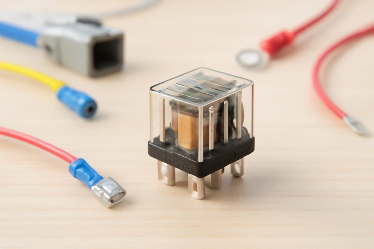
The Correct Term Is Double-Pole Double-Throw
“Double pull double throw relay” is a common search phrase, but it is not the standard expansion of DPDT. The correct technical term is double-pole double-throw relay, or DPDT relay. Manufacturer documentation likewise uses “double-pole double-throw” for this contact topology, including NI’s explanation of DPDT switching.
The short definition is:
- Double-pole: The relay switches two common electrical paths.
- Double-throw: Each common path can connect to one of two contacts.
A pole is the common path being switched. A throw is one of the available contacts to which that common can connect. A DPDT relay therefore has two poles, and each pole can select between two throws.
The relay mechanism operates both poles together. When the coil changes the relay’s state, both common contacts transfer from one set of throws to the other. Conceptually, a DPDT relay resembles two SPDT contact sets actuated by one mechanism.
“Pole A” and “Pole B” are conceptual labels, not universal terminal names. Their locations, numbering, and orientation depend on the relay model. A diagram for one product must not be applied to another relay merely because the packages look similar.
DPDT also describes only the contact arrangement. It does not specify:
- Coil voltage or current
- Physical pin layout
- Terminal numbering
- Contact voltage or current ratings
- Suitability for a particular type of load
- Enclosure or mounting style
- Contact-transfer behavior
- Internal coil suppression
- Environmental suitability
Two relays can both be DPDT devices while having different coil requirements, contact capabilities, package layouts, and operating limits. The topology explains what switching arrangement is available; it does not establish whether a particular relay is suitable for a motor, actuator, vehicle, trailer, or other installation.
Inside a DPDT Relay: Coil, COM, NC, and NO
An electromechanical DPDT relay has two functional sides:
- The control side, which includes the coil
- The contact side, which includes two changeover contact sets
Applying the relay’s specified control voltage to the coil operates the mechanism. The contacts then switch the external circuits. The control and contact sides belong to the same device, but their voltage and current requirements are separate specifications.
Each pole has three functional contact connections:
- COM: Common
- NC: Normally closed
- NO: Normally open
Here, normal means the coil’s de-energized state. It does not mean the state in which the connected machine, motor, or actuator normally operates.
When the coil is energized, each COM transfers to its corresponding NO contact. Both poles are operated by the same relay mechanism.
The following is a conceptual contact-state table, not a physical terminal map:
| Coil state | Pole A connection | Pole B connection |
|---|---|---|
| De-energized | COM A to NC A | COM B to NC B |
| Energized | COM A to NO A | COM B to NO B |
The same arrangement can be represented as:
Conceptual DPDT contact arrangement

Pole A:  NC A ← COM A → NO A
Pole B:  NC B ← COM B → NO B

Coil off: COM A selects NC A; COM B selects NC B
Coil on:  COM A selects NO A; COM B selects NO B
This illustration intentionally omits pin numbers. The DPDT designation does not create a universal terminal map. Use the diagram printed on the exact relay case or the manufacturer’s datasheet to identify the coil, COM, NC, and NO connections.
The two poles remain separate switching paths even though one mechanism operates them together. That makes it possible to switch two coordinated paths without automatically joining their common terminals. Any allowable voltage differences, insulation requirements, or contact loads remain product-specific.
Why DPDT relays are called both six-terminal and eight-terminal devices
Pin-count descriptions can be confusing because they do not always count the same functions.
The two changeover contact sets require six functional contact connections:
- Two COM connections
- Two NC connections
- Two NO connections
A mechanical DPDT switch may therefore be described as a six-terminal device because it has no separate relay coil. A manufacturer knowledge-base article, for example, describes the typical six-terminal DPDT switch form.
A conventional electromechanical DPDT relay may expose those six contact connections plus two coil connections, producing eight external connections. This conventional eight-connection arrangement is also described in a community discussion of relay pin counts and polarity reversal. That discussion illustrates a common package, not a universal rule.
Neither “six-terminal” nor “eight-terminal” should be used as a substitute for the product documentation. Some descriptions count only contacts, and specialized packages may expose their functions differently. Identify every connection from the exact case diagram or datasheet rather than from a generic product photograph.
How DPDT Contacts Can Reverse DC Polarity
A compatible two-wire permanent-magnet DC motor can change direction when the polarity across its two leads is reversed. A compatible two-wire linear actuator can use the same principle: one polarity produces movement in one direction, while the opposite polarity produces movement in the other.
From a single-ended DC supply, a complete polarity reversal requires the two load conductors to exchange their positive and negative relationships. A DPDT relay can perform that exchange because it supplies two changeover poles.
When the contacts are cross-connected in a suitable, product-specific circuit:
- One relay state makes Motor Lead A positive relative to Motor Lead B.
- The other state makes Motor Lead B positive relative to Motor Lead A.
The electrical result can be summarized without assigning physical relay pins:
| Relay state | Motor Lead A | Motor Lead B | Resulting polarity |
|---|---|---|---|
| State 1 | Positive relative to B | Negative relative to A | A-to-B |
| State 2 | Negative relative to B | Positive relative to A | B-to-A |
This is a conceptual polarity table, not a construction-ready wiring diagram. The necessary contact assignments depend on the exact relay and must be checked against its documentation.
A seller example describes a DPDT relay as a device for reversing polarity to a DC motor or linear actuator. That establishes the intended application claimed for that product, but it does not validate a universal pin arrangement or prove suitability for a different load.
A separate All About Circuits discussion describes a 12 V linear-actuator project using a DPDT relay and timer. Because it is a community discussion and its attached wiring diagram is not available in the supplied material, it should be treated only as an application example.
The relay itself does not inherently define:
- Clockwise or counterclockwise
- Forward or reverse
- Extend or retract
- Open or close
Those labels belong to the application. The resulting motion depends on the motor or actuator wiring and the polarity applied to its leads.
Polarity reversal is not necessarily three-state control
One DPDT relay can perform a two-polarity swap, but a basic changeover arrangement does not automatically provide three states.
It may provide only:
- Coil de-energized: one polarity
- Coil energized: the opposite polarity
Removing coil power selects the NC contacts; it does not inherently disconnect the load. If both sets of throws form powered load paths, the relay may select one direction when de-energized and the other when energized.
That can fit an application intended to alternate between two directions. It does not, by itself, meet a requirement for separate forward, reverse, and stop commands. If the application needs a true off state, that state must be deliberately provided by the complete control arrangement.
Do not turn the conceptual polarity table into a jumper pattern or transfer terminal numbers from another relay. If the available manufacturer documentation does not clearly identify the terminals and supported application, do not energize the proposed circuit on the basis of a generic diagram.
One DPDT Relay Versus Two SPDT Relays
An SPDT relay is a single-pole double-throw relay. It has one common contact that transfers between an NC contact and an NO contact.
A conventional five-connection automotive-style SPDT relay is commonly described as having two coil connections and one COM, one NC, and one NO contact. It therefore supplies one changeover pole, not two. A community engineering discussion explains why this five-connection SPDT arrangement cannot independently exchange both motor conductors from a single-ended supply.
Two SPDT relays can provide two changeover contact sets, with each relay supplying one pole. Functionally, that can provide the number of contact paths needed for polarity reversal. It does not make two independent relays mechanically identical to one DPDT relay.
| Feature | One DPDT relay | Two SPDT relays |
|---|---|---|
| Coils | One | Two |
| Changeover contact sets | Two | One per relay |
| Mechanical operation | Both poles use one mechanism | Each relay has its own mechanism |
| Basic wiring | Usually fewer separate control connections | More separate connections to define |
| Control | One coil selects the linked contact state | Both coil states must be defined |
| Possible combinations | Two linked contact states | Four on/off coil combinations |
| Transfer relationship | Poles are mechanically linked | Relays operate independently |
Actual coil current and switching times are product specifications, not properties that can be calculated from the abbreviations alone.
A user-generated comparison suggests that two SPDT relays may require more total coil current and may not switch at exactly the same time. Those observations are discussed in a Quora comparison of DPDT and separate relays, but they should be treated as design questions rather than universal measurements. The exact current and timing must come from the selected relays’ manufacturer documentation.
With two independent relays, the designer must define what each coil combination is intended to do:
- Both coils de-energized
- Relay 1 energized and Relay 2 de-energized
- Relay 1 de-energized and Relay 2 energized
- Both coils energized
The result of each combination depends on the circuit. The mere presence of two SPDT contact sets does not prove that every command combination has been deliberately handled.
This matters when a project uses separate direction commands or timer outputs. A single DPDT relay offers one coil command that selects between two linked contact states. Two SPDT relays provide independent control inputs, which creates more possible combinations that must be evaluated using the actual circuit and relay documentation.
Automotive-style DPDT products have existed. In a January 2021 DigiKey forum exchange, a DigiKey employee said that the distributor offered some DPDT automotive relays at that time. That dated statement is not evidence of current inventory, and it does not show that any particular product is suitable for a given motor.
Coil Voltage and Contact Ratings Are Different Specifications
A relay with a 12 V coil does not automatically work with every 12 V motor.
Relay specifications describe different functions:
| Specification | What it describes |
|---|---|
| Contact configuration | The switching topology, such as DPDT |
| Coil or control voltage | The voltage specified to operate the relay mechanism |
| Coil current or power | The demand placed on the control circuit |
| Contact voltage rating | The voltage the contacts are listed to switch or carry under stated conditions |
| Contact current rating | The current the contacts are listed to switch or carry under stated conditions |
| Load category | The kind of load or test condition associated with the rating |
A relay can have a 12 VDC coil while its contacts carry a separate voltage rating. Two relays with the same nominal coil voltage can also have different contact specifications.
A bounded specification-reading example
Firgelli lists model FA-LB2-12DS as a DPDT relay with 12 VDC control and a seller-stated contact rating of 12 A at 30 VDC on its product page. Those figures illustrate three distinct specifications:
- DPDT: Contact configuration
- 12 VDC: Coil or control voltage
- 12 A at 30 VDC: Seller-listed contact rating
They should not be compressed into the statement, “This 12 V, 12 A relay will work with my 12 V motor.” The figures are seller claims and do not independently validate performance, approvals, or suitability for a particular motor or actuator.
The supplied product material does not provide several details that may be needed to assess an application, including:
- Readable physical terminal assignments
- Coil-current data
- Contact-material information
- Switching-life data
- Environmental limits
- Load-specific derating information
The listing also contains an unexplained 50/60 Hz entry. Because it identifies the control signal as 12 VDC without explaining the frequency entry, that entry must not be treated as evidence that the coil accepts AC.
Why the headline current number is not enough
A contact-current number must be read with the conditions attached to it. The relay documentation must be compared with the actual load documentation rather than with supply voltage alone.
The evidence available here does not establish a general motor-rating or derating formula. It therefore cannot turn a seller’s headline contact rating into a motor recommendation. If the manufacturer does not state how the contact rating applies to the proposed load, the DPDT label and nominal current figure do not fill that gap.
The same separation applies to the control side. Correct nominal voltage does not, by itself, state the coil current. Obtain both the coil requirement and the contact-side ratings from documentation for the exact manufacturer and model.
What to Verify Before Selecting or Connecting a DPDT Relay
Use the following as a preselection worksheet, not as a universal wiring prescription.
1. Define the control supply
Record:
- Nominal control voltage
- Available control current
- Whether the command comes from a switch, timer, or controller
- Which relay state is selected when the command is absent
Then compare that information with the exact coil voltage and coil-current requirements in the manufacturer documentation. A shared “12 V” label does not establish that the controller output and relay coil are compatible.
2. Obtain the exact terminal map
Identify the relay by manufacturer and model number. Obtain a readable case diagram or datasheet that identifies:
- Both coil connections
- COM A, NC A, and NO A
- COM B, NC B, and NO B
Do not infer those functions from package shape, another relay’s numbering, or a generic socket listing. If the relay is used with a socket, confirm the socket mapping from its own documentation as well.
A continuity check may help confirm documented contact states, but it should not be used to invent a terminal map when the physical view or manufacturer information is uncertain.
3. Document the load
Record the load’s:
- Nominal voltage
- Manufacturer-documented current demands
- Motor or actuator type
- Intended operating pattern
- Required direction behavior
- Installation environment
Compare those requirements with the relay manufacturer’s applicable contact information. Do not assume that a general headline rating proves suitability for a motor or actuator.
4. Define every required operating state
Decide whether the application needs:
- Direction 1 only
- Direction 2 only
- Both directions
- Both directions plus stop
- Separate direction commands
- Timer-controlled movement
- A defined state when the relay coil is not powered
A basic DPDT polarity-reversing arrangement may select between two directions without providing a disconnected state. If stop is required, it must be an explicit state of the complete circuit.
5. Check product-specific contact behavior
DPDT does not state the relay’s contact-transfer sequence or switching time. If the application depends on a particular transfer behavior, look for that property in the exact manufacturer documentation.
Do not infer break-before-make operation, ideal simultaneous transfer, or any particular timing from the letters DPDT. If a required property is absent from the documentation, treat it as unconfirmed.
6. Check for internal coil suppression
Determine whether the coil includes:
- A diode
- A resistor
- Another suppression component
- No internal suppression
The supplied seller material does not answer this question for the example relay. Do not assume that its coil terminals are interchangeable or polarity-insensitive without product documentation.
Coil transients and motor-generated transients are separate design questions. Participants in the cited linear-actuator forum suggested suppression for both the relay coil and motor, but that discussion does not establish component values or a universal protection circuit for a bidirectional motor.
7. Confirm installation requirements
Use authoritative documentation for the actual load and installation to determine the necessary:
- Circuit protection
- Wiring
- Connectors and terminals
- Relay socket
- Enclosure
- Mounting
- Environmental protection
Those choices cannot be derived from the word “DPDT.” The abbreviation describes the contact topology, not the complete installation.
If the manufacturer documentation does not provide the terminal map and ratings needed for the proposed load, do not guess.
Common DPDT Relay Mistakes and Diagnostic Questions
Treat this as a de-energized inspection and documentation checklist. If terminal identities, ratings, or possible circuit states remain uncertain, stop and obtain the exact documentation or qualified assistance.
The motor runs in only one direction
Check:
- Whether both poles are intended to transfer between NC and NO
- Whether both motor conductors were assigned from the exact relay diagram
- Whether the correct COM contacts are being used
- Whether the coil receives its specified control voltage
- Whether the case diagram matches the physical view being examined
A relay click indicates that the mechanism may be moving. It does not establish that both contact paths are correctly identified or that the load circuit is complete.
Forward and reverse labels are swapped
“Forward” and “reverse” are application-defined. The relay has two electrical states, not an inherent preferred direction.
If one state produces the opposite motion from the intended label, the relationship between the motor leads and applied polarity differs from the labeling. Correct the application documentation and connection plan using the motor or actuator manufacturer’s information.
The relay clicks, but the motor does not move
Separate the control-side question from the contact-side questions:
- Is the coil operating?
- Are the correct COM contacts identified?
- Does the documented contact path correspond to the selected state?
- Is the load circuit complete?
- Are the relay’s stated contact capabilities applicable to the proposed load?
- Are the socket and relay mappings consistent?
- Can the motor or actuator operate under its own documented requirements?
Coil operation does not prove correct contact wiring or load suitability.
The motor operates when control power is removed
Removing coil power returns the relay to its normal, de-energized state. In that state, each COM is connected to its corresponding NC contact.
If the NC paths form one of the powered polarity states, removing the command selects that state rather than turning the motor off. That behavior follows from the chosen topology and is not, by itself, evidence of a defective relay.
If the intended result is stop, the complete circuit must provide a stop state deliberately.
The circuit reverses but cannot stop between directions
A basic DPDT changeover arrangement has two contact states. If both states apply power to the motor, neither state is off.
Revisit the control requirement rather than looking for a third state hidden in the same two-state contact topology. The evidence here supports the distinction between polarity reversal and on/off control, but not a universal replacement circuit.
A five-pin relay cannot swap both motor leads
Confirm whether the device is a conventional SPDT relay. If it has one COM, one NC, and one NO contact, it provides only one changeover pole.
The second pole required for a full two-conductor exchange is not available through alternate numbering or a jumper. Another suitable changeover contact set or a different documented control arrangement is required.
A two-relay circuit behaves unexpectedly
List all four coil combinations:
- Both coils off
- Relay 1 on and Relay 2 off
- Relay 1 off and Relay 2 on
- Both coils on
Then identify the documented contact path for each combination. Do not assume that two independent relays reproduce the linked behavior of one DPDT mechanism under every command condition.
Terminal identity or ratings remain uncertain
Do not proceed on the basis of package appearance, an audible click, or a generic internet diagram. Obtain the exact manufacturer documentation for the relay and socket. If the necessary terminal map or applicable ratings remain unavailable, seek qualified assistance before connecting power.
Frequently Asked Questions
Is “double pull double throw” the same as DPDT?
It usually refers to the same device in informal wording or search queries, but it is not the standard expansion. DPDT means double-pole double-throw.
“Double-pole” means there are two common switching paths. “Double-throw” means each common can connect to one of two contacts. Use “DPDT relay” when searching manufacturer catalogs and datasheets.
How many terminals does a typical DPDT relay have?
The contact topology uses six functional contact connections: two COM, two NC, and two NO. A conventional electromechanical relay may also have two coil connections, producing eight external connections, as described in the cited community discussion of conventional relay packages.
That arrangement is common rather than universal. Some descriptions count only the six contacts, and specialized products may expose their functions differently. Always use the exact relay’s case diagram or datasheet.
Can one DPDT relay reverse a 12 V motor or linear actuator?
Yes. One properly selected and correctly connected DPDT relay can exchange the positive and negative relationships applied to the two leads of a compatible DC motor or linear actuator.
That does not mean every DPDT relay is suitable for every 12 V load. The coil requirements, contact ratings, terminal map, load characteristics, and intended operating states must all be verified. A basic two-state arrangement may also alternate between two directions without providing a separate stop state.
Can a five-pin SPDT automotive relay reverse polarity by itself?
Not in the usual single-ended, two-wire motor arrangement. A conventional five-connection SPDT relay has only one changeover pole, so it cannot independently exchange both motor conductors.
Two suitable SPDT relays can provide two changeover contact sets, but every coil combination and corresponding contact state must be defined for the actual circuit.
Does a 12 V relay coil mean the contacts are suitable for every 12 V load?
No. The 12 V coil specification describes the relay’s control side. Contact voltage, contact current, load conditions, and other product limits are separate specifications.
A relay can have the correct coil voltage and still be unsuitable for the connected motor or actuator. Compare the load documentation with the applicable contact information for the exact relay instead of relying on coil voltage or a headline current figure alone.
Conclusion
DPDT means double-pole double-throw, not “double pull double throw.” Its two linked changeover contact sets can switch two coordinated paths and can be used to reverse the polarity supplied to a compatible two-wire DC load.
The topology explains what is possible, but it does not supply universal pin numbers, guarantee a separate off state, or prove that a relay is suitable for a particular motor or actuator.
Identify every coil, COM, NC, and NO connection from the exact manufacturer documentation. Then verify the control requirements, contact specifications, load information, intended operating states, and installation requirements before connecting power.